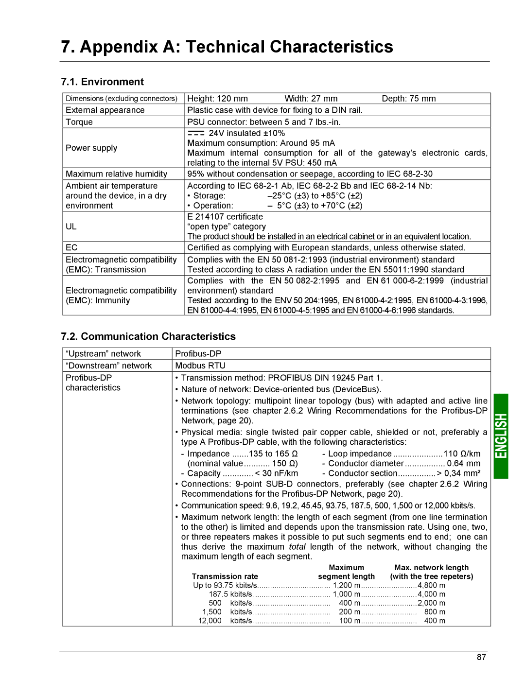
7. Appendix A: Technical Characteristics
7.1. Environment
Dimensions (excluding connectors) | Height: 120 mm | Width: 27 mm | Depth: 75 mm | |||||||
External appearance | Plastic case with device for fixing to a DIN rail. |
| ||||||||
Torque | PSU connector: between 5 and 7 |
| ||||||||
|
|
|
|
|
|
| 24V insulated ±10% |
| ||
|
|
|
|
|
|
|
| |||
|
|
|
|
|
|
|
| |||
Power supply | Maximum consumption: Around 95 mA |
| ||||||||
Maximum internal consumption for all of the gateway’s electronic cards, | ||||||||||
| ||||||||||
| relating to the internal 5V PSU: 450 mA |
| ||||||||
Maximum relative humidity | 95% without condensation or seepage, according to IEC | |||||||||
Ambient air temperature | According to IEC | |||||||||
around the device, in a dry | • Storage: |
| ||||||||
environment | • Operation: | – 5°C (±3) to +70°C (±2) |
| |||||||
UL | E 214107 certificate |
|
| |||||||
“open type” category |
|
| ||||||||
| The product should be installed in an electrical cabinet or in an equivalent location. | |||||||||
EC | Certified as complying with European standards, unless otherwise stated. | |||||||||
Electromagnetic compatibility | Complies with the EN 50 | |||||||||
(EMC): Transmission | Tested according to class A radiation under the EN 55011:1990 standard | |||||||||
| Complies with the | EN 50 | EN 61 | |||||||
Electromagnetic compatibility | environment) standard |
| ||||||||
(EMC): Immunity | Tested according to the ENV 50 204:1995, EN | |||||||||
| EN | |||||||||
7.2. Communication Characteristics
“Upstream” network |
|
|
|
|
| |
“Downstream” network | Modbus RTU |
|
|
|
|
|
• Transmission method: PROFIBUS DIN 19245 Part 1. |
|
| ||||
characteristics | • Nature of network: |
|
| |||
| • Network topology: multipoint linear topology (bus) with adapted and active line | |||||
| terminations (see chapter 2.6.2 Wiring Recommendations for the | |||||
| Network, page 20). |
|
|
|
| |
| • Physical media: single twisted pair copper cable, shielded or not, preferably a | |||||
| type A |
| ||||
| - Impedance | .......135 to 165 Ω | - Loop impedance | 110 Ω/km | ||
| (nominal value | 150 Ω) | - Conductor diameter | 0.64 mm | ||
| - Capacity | < 30 nF/km | - Conductor section | > 0,34 mm² | ||
| • Connections: | |||||
| Recommendations for the |
| ||||
| • Communication speed: 9.6, 19.2, 45.45, 93.75, 187.5, 500, 1,500 or 12,000 kbits/s. | |||||
| • Maximum network length: the length of each segment (from one line termination | |||||
| to the other) is limited and depends upon the transmission rate. Using one, two, | |||||
| or three repeaters makes it possible to put such segments end to end; one can | |||||
| thus derive the maximum total length of the network, without changing the | |||||
| maximum length of each segment. |
|
|
| ||
|
|
|
| Maximum | Max. network length | |
| Transmission rate |
| segment length | (with the tree repeters) | ||
| Up to 93.75 kbits/s | 1,200 m | 4,800 m | |||
| 187.5 kbits/s | 1,000 m | 4,000 m | |||
| 500 | kbits/s | 400 m | 2,000 m | ||
| 1,500 | kbits/s | 200 m | 800 m | ||
| 12,000 | kbits/s | 100 m | 400 m | ||
87
