Split Type
Contents
Specifications
Indoor Unit
Concealed Duct Type
RAV-SM1101BT-E RAV-SM1401BT-E
RAV-SM560AT-E RAV-SM800AT-E
Outdoor Unit
RAV-SM1100AT-E RAV-SM1400AT-E
Cooling Heating
Operation Characteristic Curve
Capacity Variation Ratio According to Temperature
Cooling
Heating
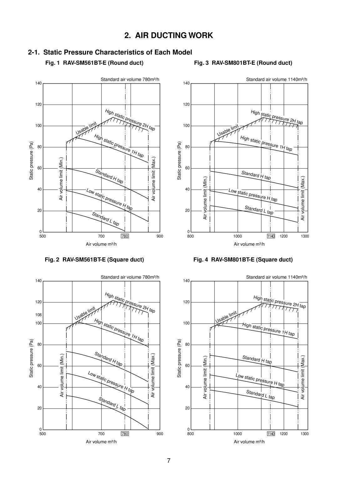
AIR Ducting Work
Static Pressure Characteristics of Each Model
RAV-SM1101BT-E Round duct
Construction Views External Views
Dimension
Indoor Unit Concealed Duct Type
RAV-SM561BT-E / SM801BT-E / SM1101BT-E / SM1401BT-E
RAV-SM560AT-E
RAV-SM800AT-E
RAV-SM1100AT-E / SM1400AT-E
Indoor Unit/Outdoor Unit
Systematic Refrigerating Cycle Diagram
Indoor unit
Outdoor unit
RAV-SM801BT-E
RAV-SM1001BT-E
Second rps Fan Indoor Outdoor
Strainer
Wiring Diagram
Color
Identification
MCC-813
Color Identification
For P.C. Board
MCC-1359
MCC-1398
MCC-1438
Parts name Type Specifications
Specifications of Electrical Parts
RAV-SM1100AT-E
Refrigerant Piping Installation
Safety During Installation/Servicing
Refrigerant R410A
Piping Materials and Joints Used
1 Thicknesses of annealed copper pipes Thickness mm
Processing of Piping Materials
Outer diameter mm R410A R22
Nominal diameter
R410A clutch type Clutch type Wing nut type
Flare tool for Conventional flare tool
R22 clutch type Clutch type Wing nut type
Diameter
Wrenches available on the market
Nm kgfcm
Tools
Required Tools
General tools Conventional tools can be used
Recharging of Refrigerant
1 Configuration of refrigerant charging
Brazing of Pipes
Materials for Brazing
Flux
Never use gas other than Nitrogen gas
Brazing
Main Sub master remote controller Weekly timer
Indoor Unit Control
Indoor Control Circuit
Control Specifications
Outline of specifications Remarks
Remote controller Outline of control Command
Operation
Heating Auto
Heat
Control temp C
Last push priority
Case of wired remote controller
Center
Operation Prohibited
Ta˚C Normal control
MCC-1402
Indoor Print Circuit Board
SM1401BT-E
RAV-SM561BT-E / SM801BT-E / SM1101BT
Function Connector Pin Specifications Remarks
Indoor P.C. Board Optional Connector Specifications
Outdoor Control
Discharge temperature release control
Outline of Main Controls
Pulse Modulating Valve PMV control
MAX
Allocations of fan tap revolutions
Outdoor fan control Object SM560
Cooling operation
Heating operation
High-pressure suppression TE control For SM800
Short intermittent operation preventive control
Over-current preventive control
Current release value shift control
Start of heating operation
Defrost control
Outdoor Controls
Print Circuit Board
MCC-813 RAV-SM560AT-E Viewed from parts of P.C board
MCC-1398 RAV-SM800AT-E / SM1100AT-E / SM1400AT-E
Summary of Troubleshooting
Troubleshooting
Wired remote controller type
Before troubleshooting
Error mode detected by indoor unit
Check Code List
Diagnostic function Cause of operation
Error mode detected by outdoor unit
Timer Ready Wired remote Controller Check code
Error mode detected by remote controller or network adapter
SW800 LED display in bit 1, bit 2, bit 3, bit 4 OFF
Error Mode Detected by LED on Outdoor P.C. Board
CDB side
Ipdu side
SW800 LED display in bit 1, bit 2, bit 3 OFF
Check code
Type a
E01 error/*99 error
Troubleshooting Procedure for Each Check Code
E09 error/*99 error
New Check Code/Present Check Code Central Control Side
E04 error/04 error
E18 error/97 error *99 error
E10 error/CF error
E08, L03, L07, L08 error/ *96 error 99 error
L09 error/46 error
L20 error/98 error
L30 error/B6 error
B7 error Central controller
F10 error 0C error
P10 error/Ob error
P12 error/11 error
P22 error/1A error
Single phase
RAV-SM1100AT-E, SM1400AT-E
F02 error/0d error
P19 error/08 error
P26 error/14 error
F01 error/0F error
H03 error/17 error
P29 error/16 error
F06 error/18 error
F04 error/19 error
F08 error/1b error
H02 error/1d error
L29 error/1C error
H01 error/1F error
P03 error/1E error
P04 error/21 error
Error Central controller
E03 error Master indoor unit
F29 error / 12 error
P31 error Sub indoor unit
Caracteristics-3
TA sensor TC, TCJ sensor Caracteristics-2 Caracteristics-1
20 TE, TO, TS sensor
TD sensor Caracteristics-4
Case
Replacement of Service Indoor P.C. Board
R2 Replacement of service P.C. board
R1 Readout of the setup data from Eeprom
Contents
Minimum requirements for item code
R3 Writing of the setup contents to Eeprom
Memorandum for setup contents Item code table Example
Type Item code
Indoor unit capacity Item code
Test Run Setup on Remote Controller
Setup AT Local Site and Others
Setup to Select Function
Wired remote controller
Description At shipment
Item No. DN table Selection of function
Cabling and Setting of Remote Controller Control
Setup method
Operation
Monitor Function of Remote Controller Switch
Contents
Procedure
Group control operation
Calling of error history
Requirement
System example
Network Address Setup Switch SW01
Microcomputer Block Diagram
LED Display Specification
Network Adapter
Communication circuit Communication cable specifications
Communication Cable Specifications
Cable Connection
Network cable connection
How to set from the remote controller at indoor unit side
How to Set an Address Number
How to set by the switch on the network adapter P.C. board
Procedure Set the network address while the unit stops
Requirement in Service
Network address No. setup table SW01
Address No
Contents Remarks
Address Setup
Address Setup
Address setup procedure
System configuration
Address Setup & Group Control
Only turning on source power supply Automatic completion
Automatic address example from unset address No miscabling
Setup completes Status returns to the usual stop status
Manual setting from remote controller
Push button if the unit stops
To know the position of indoor unit body by address
Push and buttons simultaneously for 4 seconds or more
Detachments
Part name Procedure Remarks
No. Part name Procedure Remarks
† Drain pump Remove the drain pan and float switch
Attachment
Detachment
Part name
Procedure Remarks
Requirement
Part name Procedure
Connection with the power terminal
Take off fixed screw for the valve mounting
‡ Compressor Perform works of items 1 ‚, ƒ, „, …
Fan guard
Remove the upper cabinet
Discharge port cabinet for the heat ex
Requirement
100
101
102
103
104
Product
105
106
107
108
109
110
Case of RAV-SM1100AT-E
111
Be sure to mount the propeller fan
Case of RAV-SM1400AT-E
112
113
114
Exploded Views and Parts List
Part Description
Location
115
904 901, 902, 903 35, 36, 37
RAV-SM1001BT-E / SM1401BT-E
116
RAV-SM561BT-E / SM801BT-E / SM1001BT-E / SM1401BT-E
117
118
Inverter
119
702 TE Sensor TS Sensor To Sensor TD Sensor 701 705 703 704
120
21,22 16,17
121
706
122
Inverter 26,27 23,24 28,29
123
TH Sensor