6. Configuring the Gateway
Field in the | Size in the | Description | |
frame | frame | ||
| |||
Preset Data |
| Byte swap: Specifies whether the output data bytes to be transmitted to the | |
(contd…) |
| Modbus slave must be swapped before being placed in the Modbus frame or | |
|
| not. The three possible values are as follows: | |
|
| - No swapping ....... Default configuration. The data is sent in the same order as | |
|
| they appear in the gateway’s memory. This is the case which must be used | |
|
| by default, because for an item of | |
|
| placed first in the Modbus frame and is always written into the gateway’s | |
|
| memory by a | |
|
| - Swap 2 bytes ...... The bytes to be transmitted are swapped two by two. | |
|
| - Swap 4 bytes ...... The bytes to be transmitted are swapped four by four. This is | |
|
| rarely used, as it only relates to | |
|
| previous case, “Swap 2 bytes”. | |
|
| E.g.: We will be using the “No swapping” value, because the two bytes of the | |
|
| value to be written into the ATS48’s CMD register, as transmitted by the | |
|
| TSX PBY 100 coupler, are placed into the gateway’s memory in most | |
|
| significant / least significant order. | |
Checksum | 2 bytes | Error check type: Type of error check for the frame. | |
|
| - CRC .................... Default method. This is the method adopted for the Modbus | |
|
| RTU protocol. | |
|
| - LRC ..................... This method relates to the Modbus ASCII protocol. So it | |
|
| should not be used in this case. | |
|
| - XOR .................... Simple “OR Exclusive” applied to the frame’s bytes. | |
|
| E.g.: The LUFP7 gateway is specifically designed for the Modbus protocol RTU | |
|
| mode. The default value, “CRC”, should not be changed. | |
|
| Error check start byte: Indicates the number of the byte, in the frame, from | |
|
| which the calculation of the “checksum” should begin. The first byte in each | |
|
| frame carries the number 0. | |
|
| E.g.: The calculation of a frame’s checksum should always begin with the first | |
|
| byte. The value of this field should therefore remain set to zero. |
6.11.2.5. Configuring the Content of the Response Frame
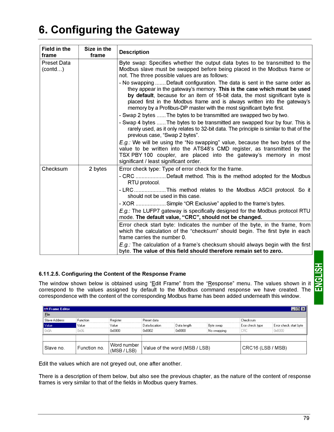
The window shown below is obtained using “Edit Frame” from the “Response” menu. The values shown in it correspond to the values assigned by default to the Modbus command response we have created. The correspondence with the content of the corresponding Modbus frame has been added underneath this window.
Slave no.
Function no.
Word number (MSB / LSB)
Value of the word (MSB / LSB)
CRC16 (LSB / MSB)
Edit the values which are not greyed out, one after another.
There is a description of them below, but also see the previous chapter, as the nature of the content of response frames is very similar to that of the fields in Modbus query frames.
79