4. Software Implementation of the Gateway
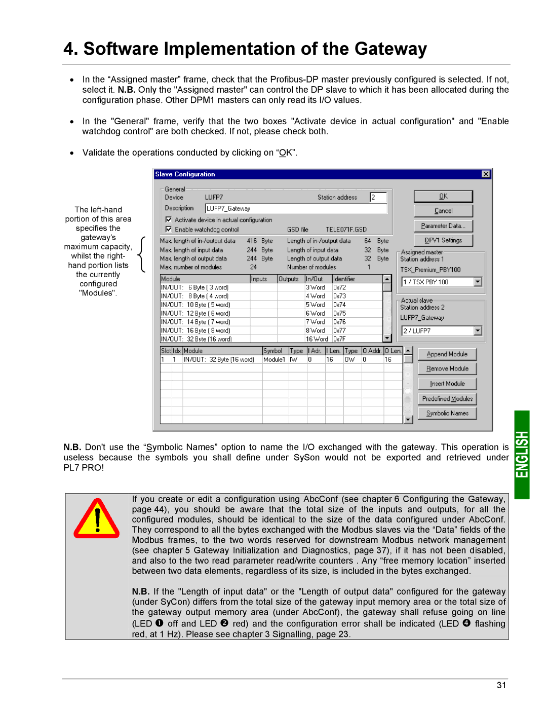
•In the “Assigned master” frame, check that the
•In the "General" frame, verify that the two boxes "Activate device in actual configuration" and "Enable watchdog control" are both checked. If not, please check both.
•Validate the operations conducted by clicking on “OK”.
The
portion of this area
specifies the
gateway's
maximum capacity,
whilst the right-
hand portion lists
the currently
configured "Modules".
N.B. Don't use the “Symbolic Names” option to name the I/O exchanged with the gateway. This operation is useless because the symbols you shall define under SySon would not be exported and retrieved under PL7 PRO!
If you create or edit a configuration using AbcConf (see chapter 6 Configuring the Gateway, page 44), you should be aware that the total size of the inputs and outputs, for all the configured modules, should be identical to the size of the data configured under AbcConf. They correspond to all the bytes exchanged with the Modbus slaves via the “Data” fields of the Modbus frames, to the two words reserved for downstream Modbus network management (see chapter 5 Gateway Initialization and Diagnostics, page 37), if it has not been disabled, and also to the two read parameter read/write counters . Any “free memory location” inserted between two data elements, regardless of its size, is included in the bytes exchanged.
N.B. If the "Length of input data" or the "Length of output data" configured for the gateway (under SyCon) differs from the total size of the gateway input memory area or the total size of the gateway output memory area (under AbcConf), the gateway shall refuse going on line
(LED n off and LED o red) and the configuration error shall be indicated (LED q flashing red, at 1 Hz). Please see chapter 3 Signalling, page 23.
31
