6. Configuring the Gateway
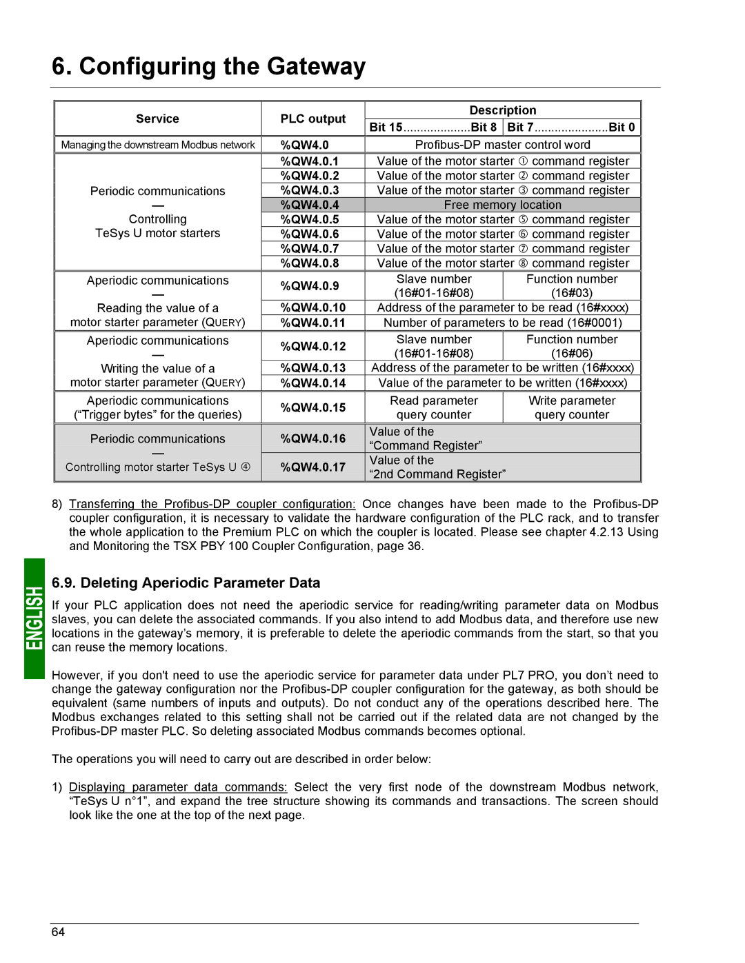
Service | PLC output | Description | |||
Bit 15....................Bit 8 |
| Bit 7......................Bit 0 | |||
|
|
|
| ||
Managing the downstream Modbus network | %QW4.0 |
| |||
| %QW4.0.1 | Value of the motor starter c command register | |||
Periodic communications | %QW4.0.2 | Value of the motor starter d command register | |||
%QW4.0.3 | Value of the motor starter e command register | ||||
— | %QW4.0.40 |
| Free memory location | ||
Controlling | %QW4.0.5 |
| Value of the motor starter g command register | ||
TeSys U motor starters | %QW4.0.6 | Value of the motor starter h command register | |||
| %QW4.0.7 | Value of the motor starter i command register | |||
| %QW4.0.8 | Value of the motor starter j command register | |||
Aperiodic communications | %QW4.0.9 | Slave number |
| Function number | |
— |
| (16#03) | |||
|
|
| |||
Reading the value of a | %QW4.0.10 | Address of the parameter | to be read (16#xxxx) | ||
motor starter parameter (QUERY) | %QW4.0.11 | Number of parameters to be read (16#0001) | |||
Aperiodic communications | %QW4.0.12 |
| Slave number |
| Function number |
— |
|
| (16#06) | ||
|
|
| |||
Writing the value of a | %QW4.0.13 |
| Address of the parameter | to be written (16#xxxx) | |
motor starter parameter (QUERY) | %QW4.0.14 |
| Value of the parameter to be written (16#xxxx) | ||
Aperiodic communications | %QW4.0.15 |
| Read parameter |
| Write parameter |
(“Trigger bytes” for the queries) |
| query counter |
| query counter | |
|
|
| |||
Periodic communications | %QW4.0.16 |
| Value of the |
| |
| “Command Register” |
| |||
— |
|
|
| ||
%QW4.0.17 |
| Value of the |
| ||
Controlling motor starter TeSys U f |
|
| |||
| “2nd Command Register” |
| |||
|
|
|
| ||
8)Transferring the
6.9. Deleting Aperiodic Parameter Data
If your PLC application does not need the aperiodic service for reading/writing parameter data on Modbus slaves, you can delete the associated commands. If you also intend to add Modbus data, and therefore use new locations in the gateway’s memory, it is preferable to delete the aperiodic commands from the start, so that you can reuse the memory locations.
However, if you don't need to use the aperiodic service for parameter data under PL7 PRO, you don’t need to change the gateway configuration nor the
The operations you will need to carry out are described in order below:
1)Displaying parameter data commands: Select the very first node of the downstream Modbus network, “TeSys U n°1”, and expand the tree structure showing its commands and transactions. The screen should look like the one at the top of the next page.
64