PowerLogic™ PM5100 series user guideChapter
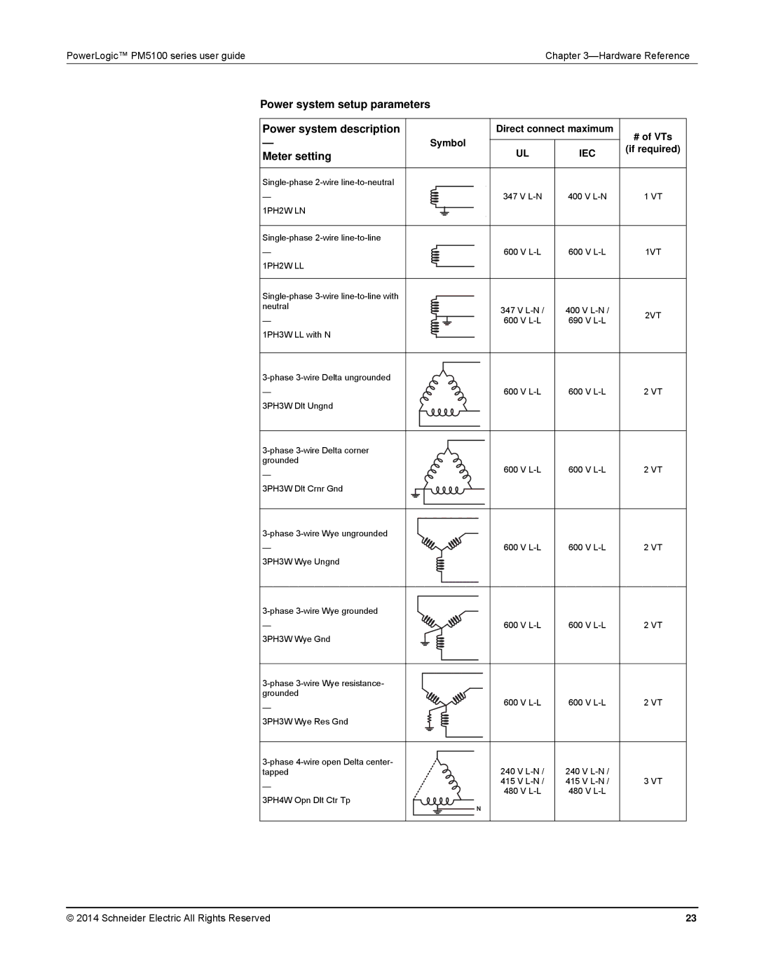
Power system setup parameters
Power system description |
| Direct connect maximum | # of VTs | |
— |
|
|
| |
Symbol |
| |||
| (if required) | |||
Meter setting |
| UL | IEC | |
|
| |||
|
|
| ||
— | 347 V | 400 V | 1 VT | |
1PH2W LN |
|
|
| |
|
|
| ||
— | 600 V | 600 V | 1VT | |
1PH2W LL |
|
|
| |
|
|
| ||
neutral | 347 V | 400 V | 2VT | |
— | ||||
600 V | 690 V | |||
| ||||
1PH3W LL with N |
|
|
| |
|
|
| ||
— | 600 V | 600 V | 2 VT | |
3PH3W Dlt Ungnd |
|
|
| |
|
|
| ||
grounded | 600 V | 600 V | 2 VT | |
— | ||||
|
|
| ||
3PH3W Dlt Crnr Gnd |
|
|
| |
|
|
| ||
— | 600 V | 600 V | 2 VT | |
3PH3W Wye Ungnd |
|
|
| |
|
|
| ||
— | 600 V | 600 V | 2 VT | |
3PH3W Wye Gnd |
|
|
| |
|
|
| ||
grounded | 600 V | 600 V | 2 VT | |
— | ||||
|
|
| ||
3PH3W Wye Res Gnd |
|
|
| |
240 V | 240 V |
| ||
tapped |
| |||
— | 415 V | 415 V | 3 VT | |
480 V | 480 V |
| ||
3PH4W Opn Dlt Ctr Tp |
| |||
N |
|
| ||
|
|
|
© 2014 Schneider Electric All Rights Reserved | 23 |