PowerLogic™ PM5100 series user guide | Chapter |
|
|
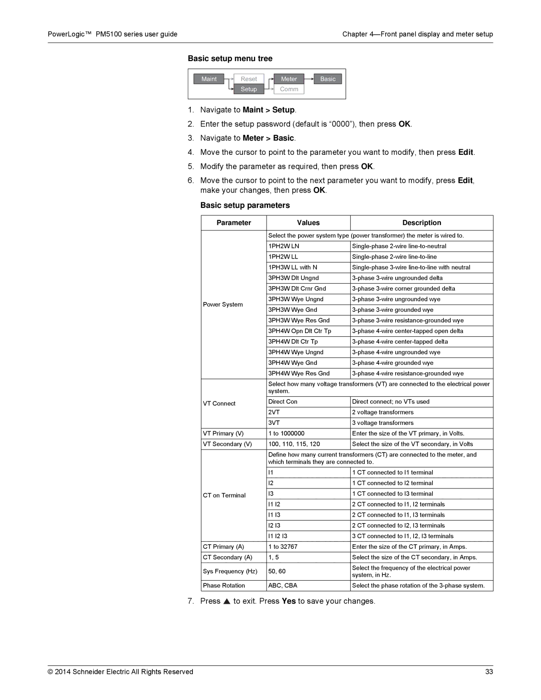
Basic setup menu tree
Maint | Reset | Meter | Basic |
| Setup | Comm |
|
1.Navigate to Maint > Setup.
2.Enter the setup password (default is “0000”), then press OK.
3.Navigate to Meter > Basic.
4.Move the cursor to point to the parameter you want to modify, then press Edit.
5.Modify the parameter as required, then press OK.
6.Move the cursor to point to the next parameter you want to modify, press Edit, make your changes, then press OK.
Basic setup parameters
Parameter | Values | Description | |
|
|
| |
| Select the power system type (power transformer) the meter is wired to. | ||
|
|
| |
| 1PH2W LN | ||
|
|
| |
| 1PH2W LL | ||
|
|
| |
| 1PH3W LL with N | ||
|
|
| |
| 3PH3W Dlt Ungnd | ||
|
|
| |
| 3PH3W Dlt Crnr Gnd | ||
|
|
| |
Power System | 3PH3W Wye Ungnd | ||
|
| ||
3PH3W Wye Gnd | |||
| |||
|
|
| |
| 3PH3W Wye Res Gnd | ||
|
|
| |
| 3PH4W Opn Dlt Ctr Tp | ||
|
|
| |
| 3PH4W Dlt Ctr Tp | ||
|
|
| |
| 3PH4W Wye Ungnd | ||
|
|
| |
| 3PH4W Wye Gnd | ||
|
|
| |
| 3PH4W Wye Res Gnd | ||
|
|
| |
| Select how many voltage transformers (VT) are connected to the electrical power | ||
| system. |
| |
VT Connect | Direct Con | Direct connect; no VTs used | |
| 2VT | 2 voltage transformers | |
|
|
| |
| 3VT | 3 voltage transformers | |
|
|
| |
VT Primary (V) | 1 to 1000000 | Enter the size of the VT primary, in Volts. | |
|
|
| |
VT Secondary (V) | 100, 110, 115, 120 | Select the size of the VT secondary, in Volts | |
|
|
| |
| Define how many current transformers (CT) are connected to the meter, and | ||
| which terminals they are connected to. | ||
| I1 | 1 CT connected to I1 terminal | |
|
|
| |
| I2 | 1 CT connected to I2 terminal | |
|
|
| |
CT on Terminal | I3 | 1 CT connected to I3 terminal | |
| I1 I2 | 2 CT connected to I1, I2 terminals | |
|
|
| |
| I1 I3 | 2 CT connected to I1, I3 terminals | |
|
|
| |
| I2 I3 | 2 CT connected to I2, I3 terminals | |
|
|
| |
| I1 I2 I3 | 3 CT connected to I1, I2, I3 terminals | |
|
|
| |
CT Primary (A) | 1 to 32767 | Enter the size of the CT primary, in Amps. | |
|
|
| |
CT Secondary (A) | 1, 5 | Select the size of the CT secondary, in Amps. | |
|
|
| |
Sys Frequency (Hz) | 50, 60 | Select the frequency of the electrical power | |
system, in Hz. | |||
|
| ||
Phase Rotation | ABC, CBA | Select the phase rotation of the | |
|
|
| |
7. Press  to exit. Press Yes to save your changes.
© 2014 Schneider Electric All Rights Reserved | 33 |