PowerLogic™ PM5100 series | Chapter |
|
|
Related topics
•See “Meter mounting” on page 17 and “Meter wiring” on page 19 for additional information.
Installing the terminal covers
The voltage and current terminal covers help prevent tampering with the meter’s voltage and current measurement inputs. The terminal covers enclose the terminals, the conductor fixing screws and a suitable length of the external conductors and their insulation. The terminal covers are secured by
The meter terminal covers must be installed by a qualified installer. The installation of both the voltage and current terminal covers is required to provide tamper evidence for MID installations.
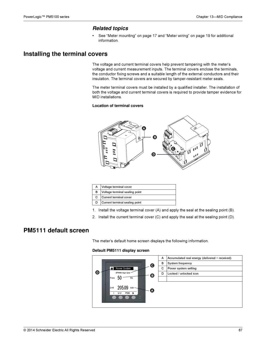
Location of terminal covers
![]()
![]()
![]()
![]()
![]()
![]()
![]()
![]()
![]()
![]() A
A
B
![]()
![]()
![]()
![]()
![]()
![]()
![]()
![]() C
C![]()
![]()
![]()
D
AVoltage terminal cover
BVoltage terminal sealing point
CCurrent terminal cover
DCurrent terminal sealing point
1.Install the voltage terminal cover (A) and apply the seal at the sealing point (B).
2.Install the current terminal cover (C) and apply the seal at the sealing point (D).
PM5111 default screen
The meter’s default home screen displays the following information.
Default PM5111 display screen
C
D![]()
![]() B
B
AAccumulated real energy (delivered + received)
BSystem frequency
CPower system setting
DLocked / unlocked icon
![]() A
A
© 2014 Schneider Electric All Rights Reserved | 87 |