Interfaces |
DTR protocol
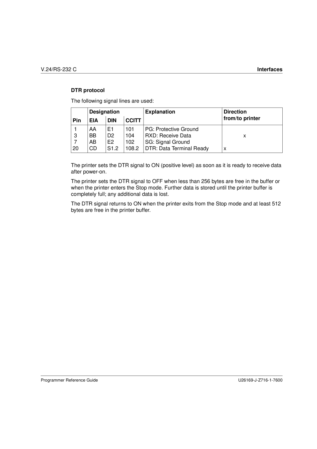
The following signal lines are used:
| Designation |
|
| Explanation | Direction | ||
Pin | EIA |
| DIN |
| CCITT |
| from/to printer |
|
|
| |||||
|
|
|
| ||||
|
|
|
|
|
|
|
|
1 | AA |
| E1 |
| 101 | PG: Protective Ground |
|
3 | BB |
| D2 |
| 104 | RXD: Receive Data | x |
7 | AB |
| E2 |
| 102 | SG: Signal Ground |
|
20 | CD |
| S1.2 |
| 108.2 | DTR: Data Terminal Ready | x |
|
|
|
|
|
|
|
|
The printer sets the DTR signal to ON (positive level) as soon as it is ready to receive data after
The printer sets the DTR signal to OFF when less than 256 bytes are free in the buffer or when the printer enters the Stop mode. Further data is stored until the printer buffer is completely full; any additional data is lost.
The DTR signal returns to ON when the printer exits from the Stop mode and at least 512 bytes are free in the printer buffer.
Programmer Reference Guide |
