CentronicsInterfaces
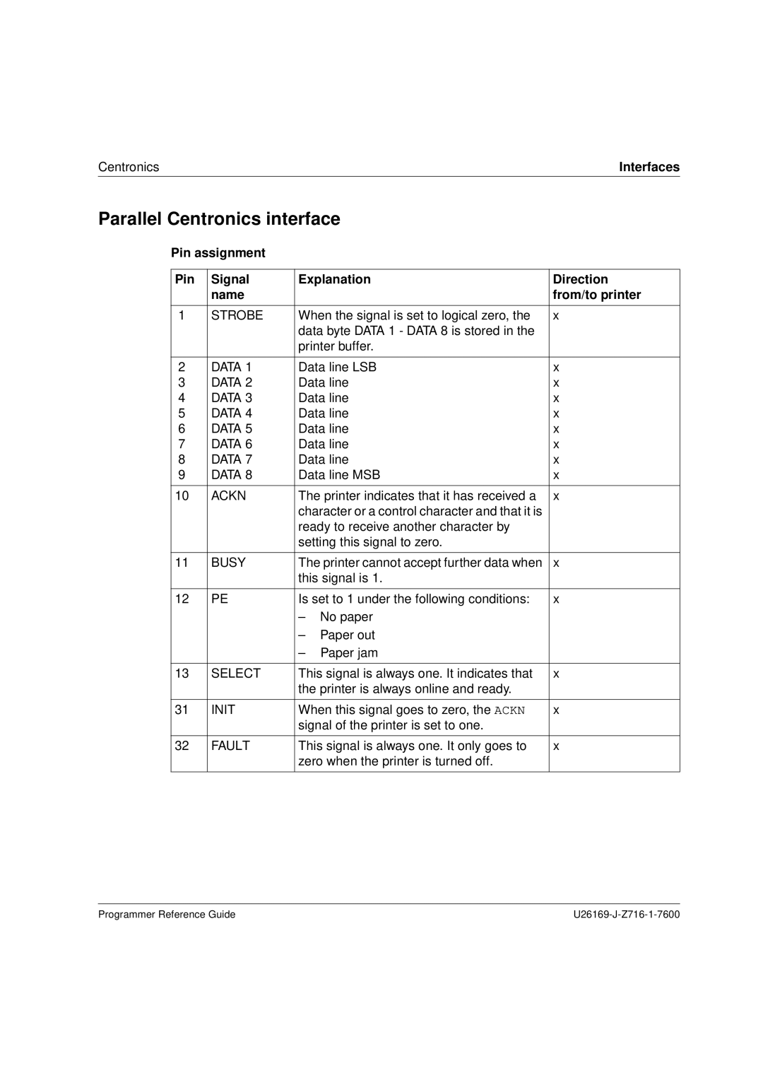
Parallel Centronics interface
Pin assignment
Pin | Signal | Explanation | Direction | |
| name |
|
| from/to printer |
|
|
|
| |
1 | STROBE | When the signal is set to logical zero, the | x | |
|
| data byte DATA 1 - DATA 8 is stored in the |
| |
|
| printer buffer. |
| |
|
|
|
| |
2 | DATA 1 | Data line LSB | x | |
3 | DATA 2 | Data line | x | |
4 | DATA 3 | Data line | x | |
5 | DATA 4 | Data line | x | |
6 | DATA 5 | Data line | x | |
7 | DATA 6 | Data line | x | |
8 | DATA 7 | Data line | x | |
9 | DATA 8 | Data line MSB | x | |
|
|
|
| |
10 | ACKN | The printer indicates that it has received a | x | |
|
| character or a control character and that it is |
| |
|
| ready to receive another character by |
| |
|
| setting this signal to zero. |
| |
|
|
|
| |
11 | BUSY | The printer cannot accept further data when | x | |
|
| this signal is 1. |
| |
|
|
|
| |
12 | PE | Is set to 1 under the following conditions: | x | |
|
| – | No paper |
|
|
| – | Paper out |
|
|
| – | Paper jam |
|
|
|
|
| |
13 | SELECT | This signal is always one. It indicates that | x | |
|
| the printer is always online and ready. |
| |
|
|
|
| |
31 | INIT | When this signal goes to zero, the ACKN | x | |
|
| signal of the printer is set to one. |
| |
|
|
|
| |
32 | FAULT | This signal is always one. It only goes to | x | |
|
| zero when the printer is turned off. |
| |
|
|
|
|
|
Programmer Reference Guide |
