SETTINGS AND ADJUSTMENTS
SECTION 4-14
Adjusting or Replacing Rotor Knives
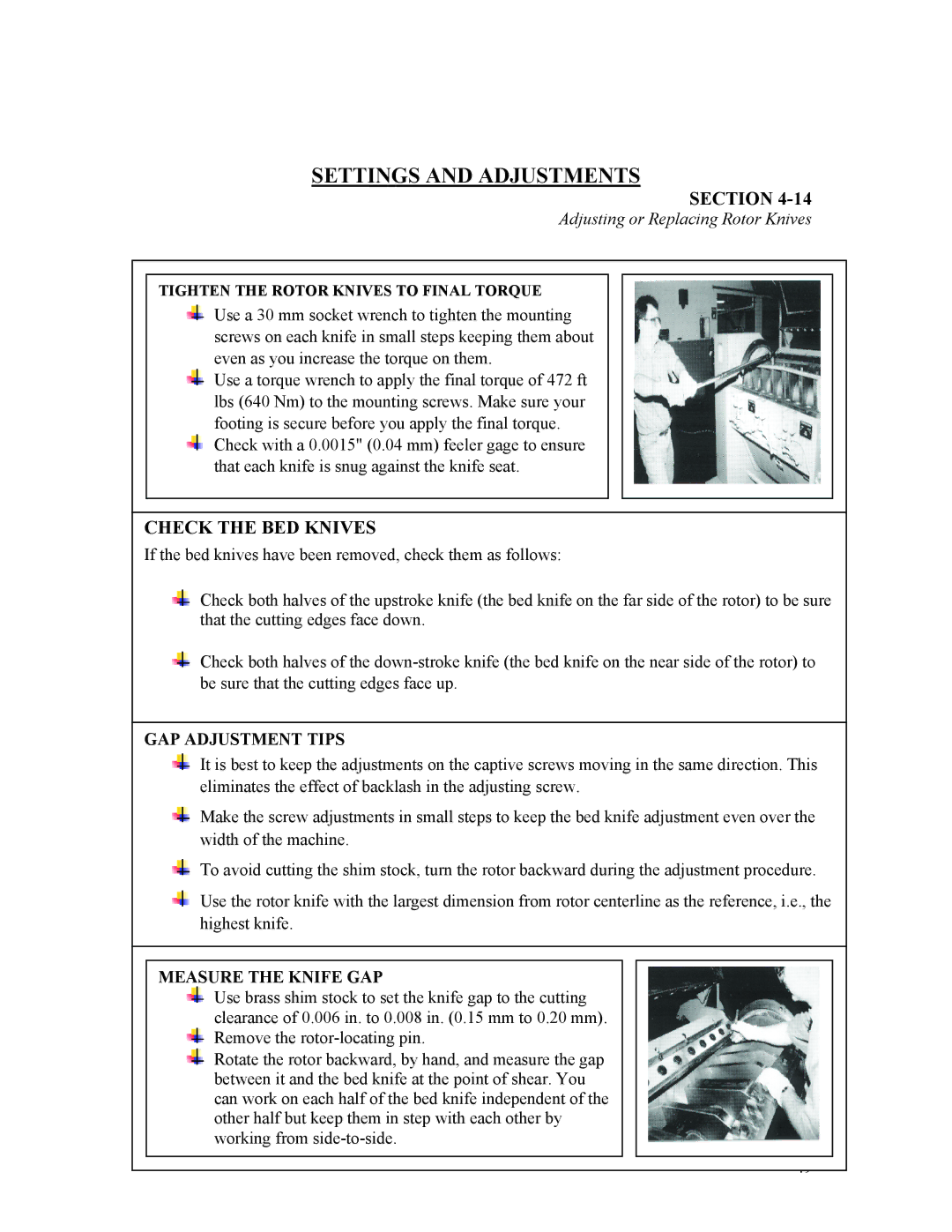
TIGHTEN THE ROTOR KNIVES TO FINAL TORQUE
Use a 30 mm socket wrench to tighten the mounting screws on each knife in small steps keeping them about even as you increase the torque on them.
Use a torque wrench to apply the final torque of 472 ft lbs (640 Nm) to the mounting screws. Make sure your footing is secure before you apply the final torque.
Check with a 0.0015" (0.04 mm) feeler gage to ensure that each knife is snug against the knife seat.
CHECK THE BED KNIVES
If the bed knives have been removed, check them as follows:
Check both halves of the upstroke knife (the bed knife on the far side of the rotor) to be sure that the cutting edges face down.
Check both halves of the
GAP ADJUSTMENT TIPS
It is best to keep the adjustments on the captive screws moving in the same direction. This eliminates the effect of backlash in the adjusting screw.
Make the screw adjustments in small steps to keep the bed knife adjustment even over the width of the machine.
To avoid cutting the shim stock, turn the rotor backward during the adjustment procedure.
Use the rotor knife with the largest dimension from rotor centerline as the reference, i.e., the highest knife.
MEASURE THE KNIFE GAP
Use brass shim stock to set the knife gap to the cutting clearance of 0.006 in. to 0.008 in. (0.15 mm to 0.20 mm). Remove the
Rotate the rotor backward, by hand, and measure the gap between it and the bed knife at the point of shear. You can work on each half of the bed knife independent of the other half but keep them in step with each other by working from
49