MACHINE AND CONTROLS
SECTION 2-3
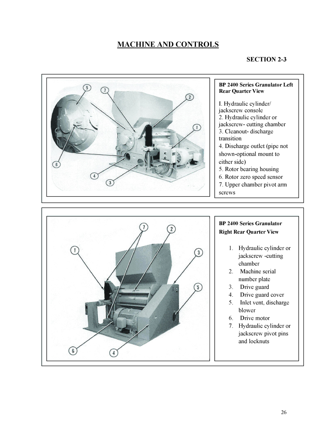
BP 2400 Series Granulator Left
Rear Quarter View
I. Hydraulic cylinder/ jackscrew console
2. Hydraulic cylinder or jackscrew- cutting chamber 3. Cleanout- discharge transition
4. Discharge outlet (pipe not
5. Rotor bearing housing
6. Rotor zero speed sensor
7. Upper chamber pivot arm screws
BP 2400 Series Granulator
Right Rear Quarter View
1. Hydraulic cylinder or jackscrew
2. Machine serial number plate
3. Drive guard
4. Drive guard cover
5. Inlet vent, discharge blower
6. Drive motor
7. Hydraulic cylinder or jackscrew pivot pins and locknuts
26