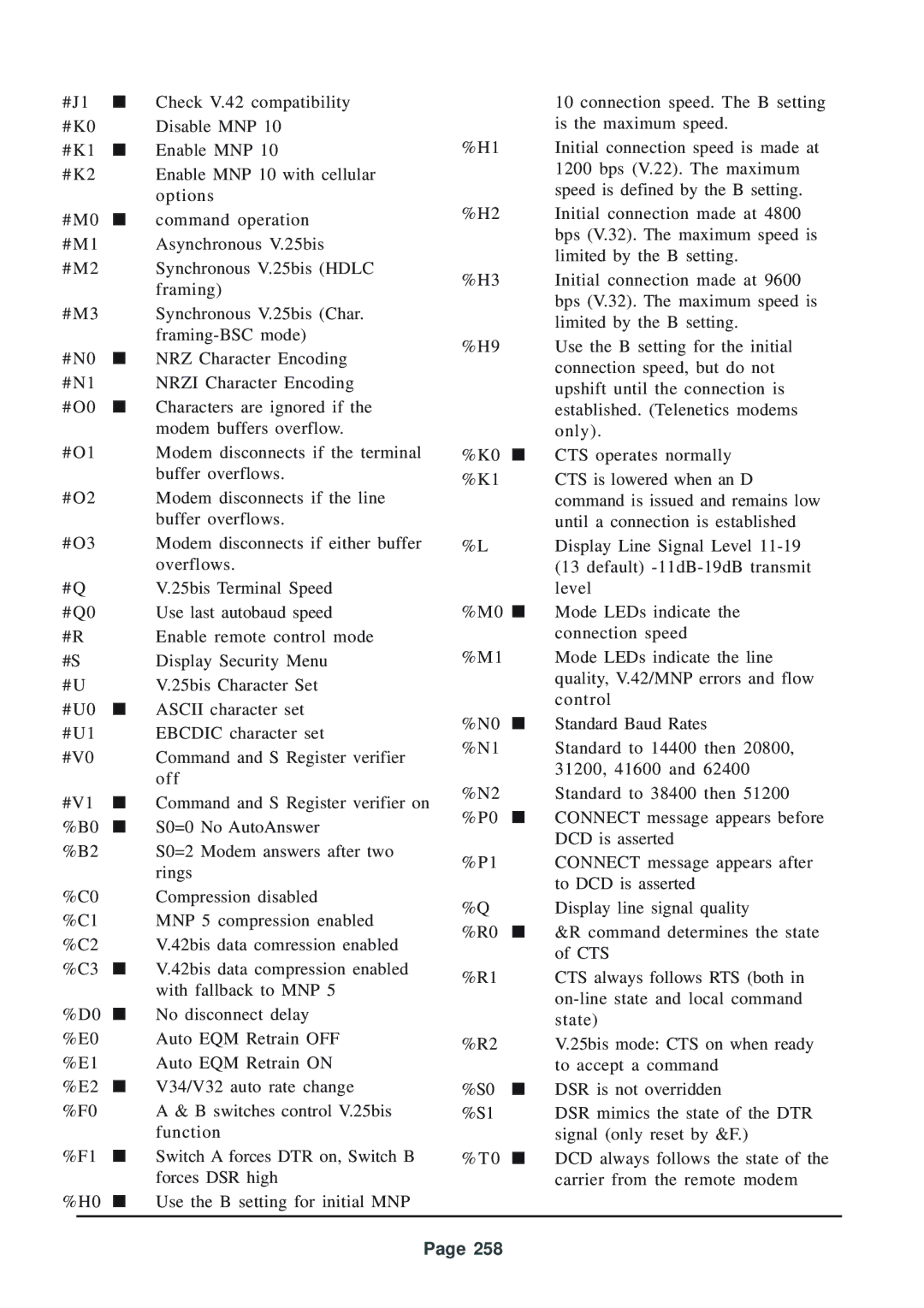
#J1 | ■ | Check V.42 compatibility |
#K0 |
| Disable MNP 10 |
#K1 | ■ | Enable MNP 10 |
#K2 |
| Enable MNP 10 with cellular |
|
| options |
#M0 | ■ | command operation |
#M1 |
| Asynchronous V.25bis |
#M2 |
| Synchronous V.25bis (HDLC |
|
| framing) |
#M3 |
| Synchronous V.25bis (Char. |
|
| |
#N0 | ■ | NRZ Character Encoding |
#N1 |
| NRZI Character Encoding |
#O0 | ■ | Characters are ignored if the |
|
| modem buffers overflow. |
#O1 |
| Modem disconnects if the terminal |
|
| buffer overflows. |
#O2 |
| Modem disconnects if the line |
|
| buffer overflows. |
#O3 |
| Modem disconnects if either buffer |
|
| overflows. |
#Q |
| V.25bis Terminal Speed |
#Q0 |
| Use last autobaud speed |
#R |
| Enable remote control mode |
#S |
| Display Security Menu |
#U |
| V.25bis Character Set |
#U0 | ■ | ASCII character set |
#U1 |
| EBCDIC character set |
#V0 |
| Command and S Register verifier |
|
| off |
#V1 | ■ | Command and S Register verifier on |
%B0 | ■ | S0=0 No AutoAnswer |
%B2 |
| S0=2 Modem answers after two |
|
| rings |
%C0 |
| Compression disabled |
%C1 |
| MNP 5 compression enabled |
%C2 |
| V.42bis data comression enabled |
%C3 | ■ | V.42bis data compression enabled |
|
| with fallback to MNP 5 |
%D0 | ■ | No disconnect delay |
%E0 |
| Auto EQM Retrain OFF |
%E1 |
| Auto EQM Retrain ON |
%E2 | ■ | V34/V32 auto rate change |
%F0 |
| A & B switches control V.25bis |
|
| function |
%F1 | ■ | Switch A forces DTR on, Switch B |
|
| forces DSR high |
%H0 | ■ | Use the B setting for initial MNP |
|
| 10 connection speed. The B setting |
|
| is the maximum speed. |
%H1 |
| Initial connection speed is made at |
|
| 1200 bps (V.22). The maximum |
|
| speed is defined by the B setting. |
%H2 |
| Initial connection made at 4800 |
|
| bps (V.32). The maximum speed is |
|
| limited by the B setting. |
%H3 |
| Initial connection made at 9600 |
|
| bps (V.32). The maximum speed is |
|
| limited by the B setting. |
%H9 |
| Use the B setting for the initial |
|
| connection speed, but do not |
|
| upshift until the connection is |
|
| established. (Telenetics modems |
|
| only). |
%K0 | ■ | CTS operates normally |
%K1 |
| CTS is lowered when an D |
|
| command is issued and remains low |
|
| until a connection is established |
%L |
| Display Line Signal Level |
|
| (13 default) |
|
| level |
%M0 ■ | Mode LEDs indicate the | |
|
| connection speed |
%M1 |
| Mode LEDs indicate the line |
|
| quality, V.42/MNP errors and flow |
|
| control |
%N0 | ■ | Standard Baud Rates |
%N1 |
| Standard to 14400 then 20800, |
|
| 31200, 41600 and 62400 |
%N2 |
| Standard to 38400 then 51200 |
%P0 | ■ | CONNECT message appears before |
|
| DCD is asserted |
%P1 |
| CONNECT message appears after |
|
| to DCD is asserted |
%Q |
| Display line signal quality |
%R0 | ■ | &R command determines the state |
|
| of CTS |
%R1 |
| CTS always follows RTS (both in |
|
| |
|
| state) |
%R2 |
| V.25bis mode: CTS on when ready |
|
| to accept a command |
%S0 | ■ | DSR is not overridden |
%S1 |
| DSR mimics the state of the DTR |
|
| signal (only reset by &F.) |
%T0 | ■ | DCD always follows the state of the |
|
| carrier from the remote modem |
Page 258
