| www.ti.com |
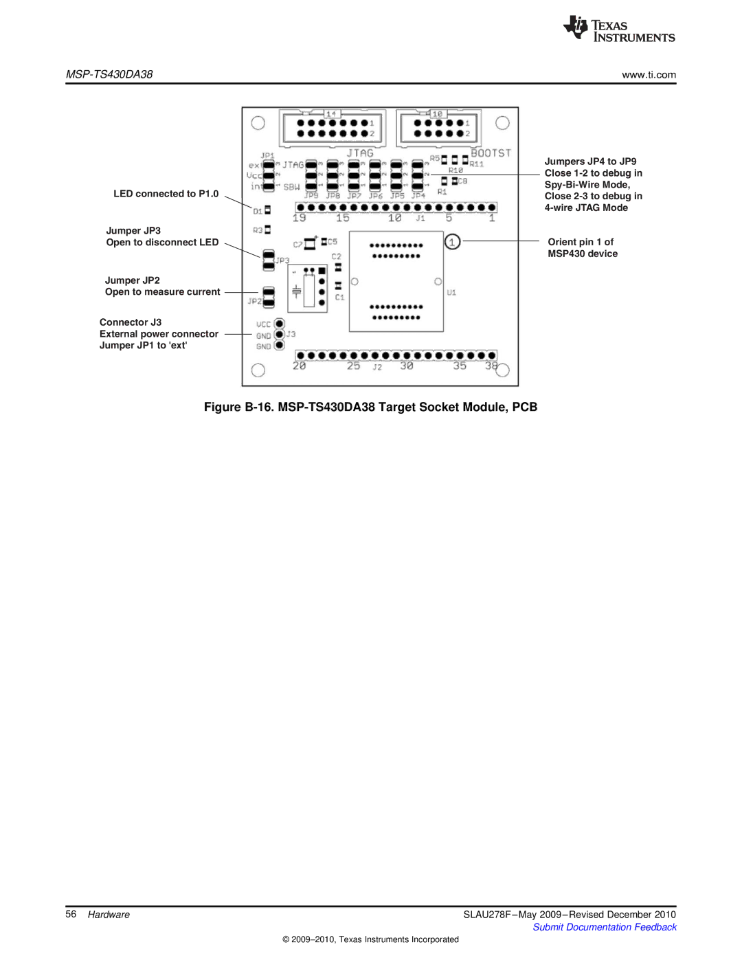
LED connected to P1.0
Jumper JP3
Open to disconnect LED
Jumper JP2
Open to measure current
Connector J3
External power connector Jumper JP1 to 'ext'
Jumpers JP4 to JP9 Close
Orient pin 1 of
MSP430 device
Figure B-16. MSP-TS430DA38 Target Socket Module, PCB
56 Hardware | SLAU278F |
| Submit Documentation Feedback |
©