| www.ti.com |
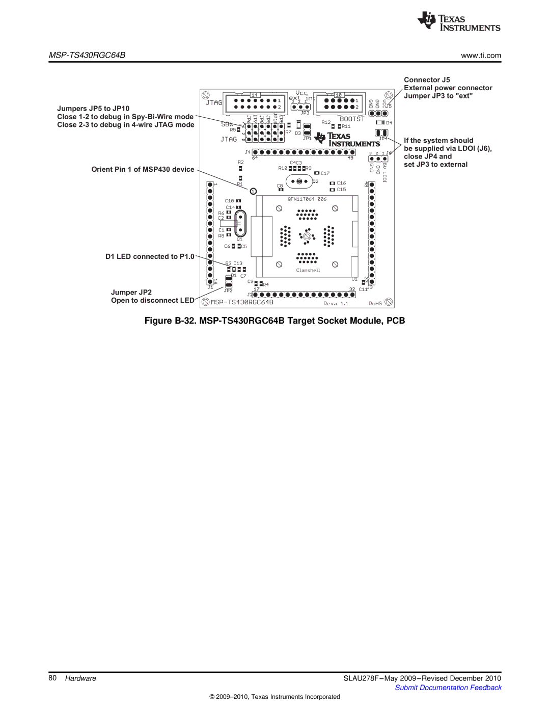
Jumpers JP5 to JP10
Close
Close
Orient Pin 1 of MSP430 device
D1 LED connected to P1.0 ![]()
Jumper JP2
Open to disconnect LED
Connector J5
External power connector Jumper JP3 to "ext"
If the system should
be supplied via LDOI (J6), close JP4 and
set JP3 to external
Figure B-32. MSP-TS430RGC64B Target Socket Module, PCB
80 Hardware | SLAU278F |
| Submit Documentation Feedback |
©