| www.ti.com |
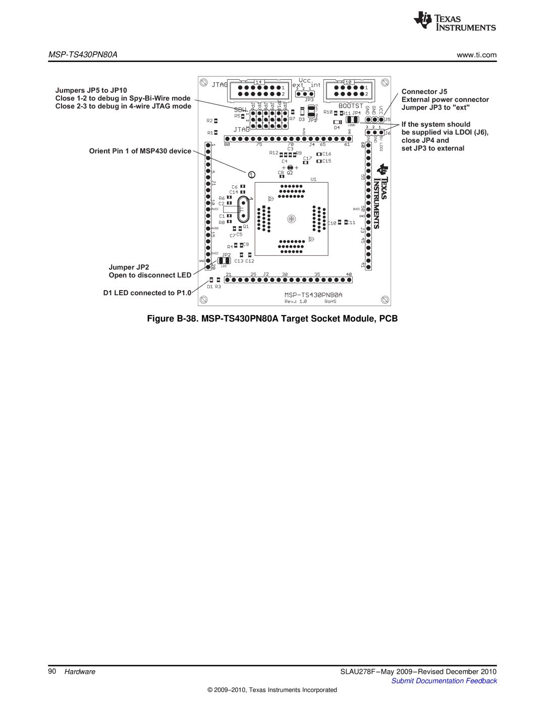
Jumpers JP5 to JP10
Close
Orient Pin 1 of MSP430 device
Jumper JP2
Open to disconnect LED
D1 LED connected to P1.0![]()
Connector J5
External power connector Jumper JP3 to "ext"
If the system should
be supplied via LDOI (J6), close JP4 and
set JP3 to external
Figure B-38. MSP-TS430PN80A Target Socket Module, PCB
90 Hardware | SLAU278F |
| Submit Documentation Feedback |
©