| www.ti.com |
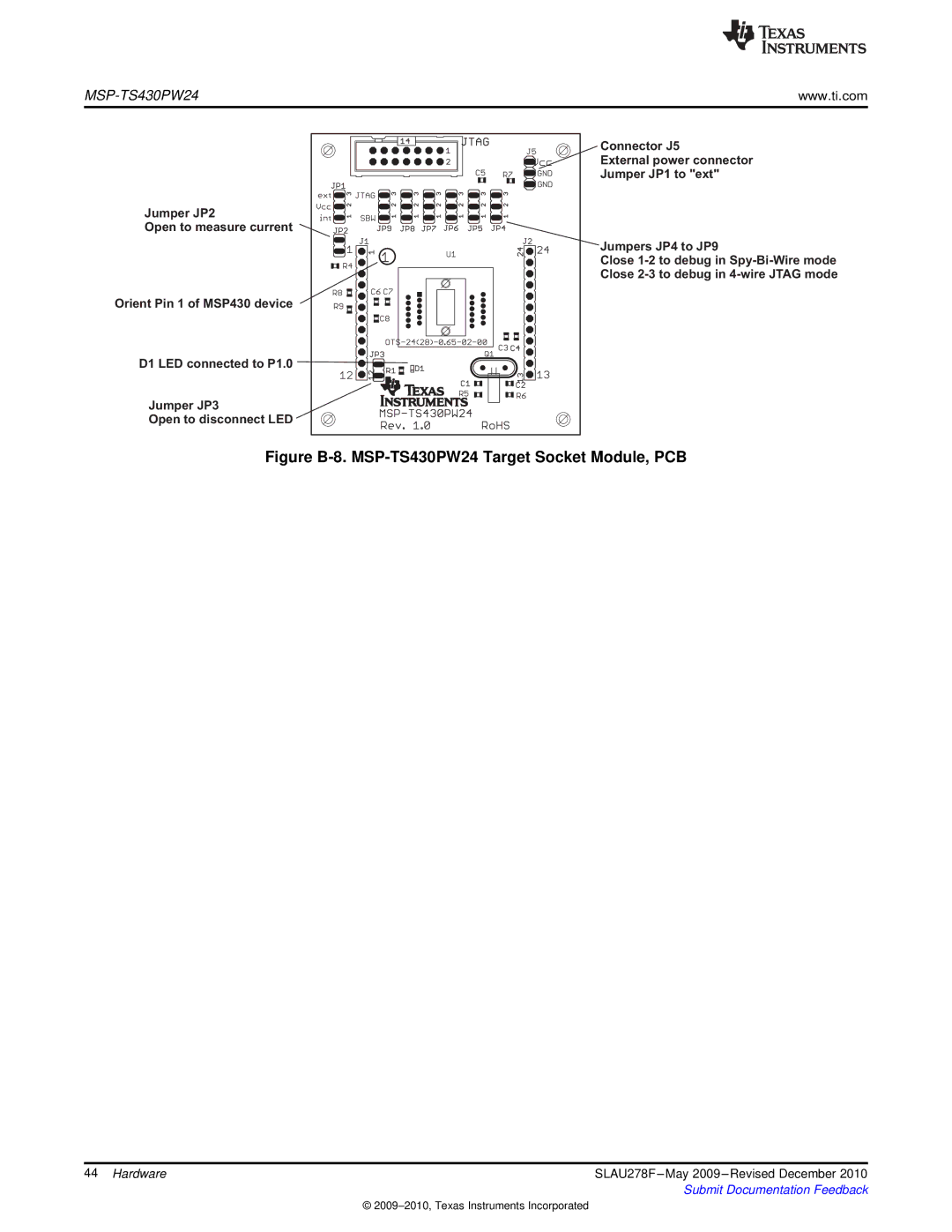
Jumper JP2
Open to measure current
Orient Pin 1 of MSP430 device
D1 LED connected to P1.0
Jumper JP3
Open to disconnect LED
Connector J5
External power connector
Jumper JP1 to "ext"
Jumpers JP4 to JP9
Close
Figure B-8. MSP-TS430PW24 Target Socket Module, PCB
44 Hardware | SLAU278F |
| Submit Documentation Feedback |
©