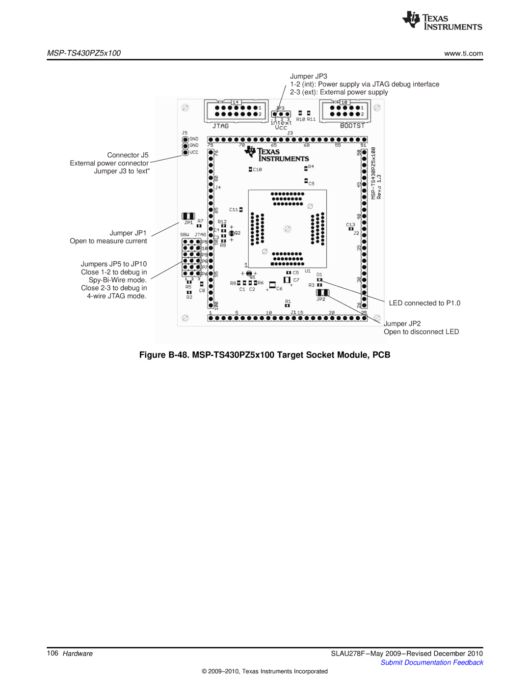
MSP-TS430PZ5x100

www.ti.com

Jumper JP3

1-2 (int): Power supply via JTAG debug interface

2-3 (ext): External power supply

Connector J5

External power connector

Jumper J3 to ‘ext’

Jumper JP1

Open to measure current

Jumpers JP5 to JP10 Close 1-2 to debug in Spy-Bi-Wire mode. Close 2-3 to debug in 4-wire JTAG mode.

LED connected to P1.0

Jumper JP2

Open to disconnect LED

Figure B-48. MSP-TS430PZ5x100 Target Socket Module, PCB

106 Hardware

SLAU278F –May 2009 –Revised December 2010


Submit Documentation Feedback

© 2009–2010, Texas Instruments Incorporated

Page 106
Image 106
Texas Instruments MSP430 manual Figure B-48. MSP-TS430PZ5x100 Target Socket Module, PCB