TNETX3270
ThunderSWITCH 24/3 ETHERNET SWITCH
WITH 24 10-MBIT/S PORTS AND 3 10-/100-MBIT/S PORTS
SPWS043B ± NOVEMBER 1997 ± REVISED APRIL 1999
EEPROM interface (continued)
Multiple bus masters are not supported on the EEPROM interface because the ECLK pin always is driven by the device with a strong 0/strong 1 (i.e., not a strong 1/resistively
An Ethernet CRC check is used to ensure the EEPROM data is valid. The
A valid CRC always must be provided by the EEPROM. The EEPROM data for the most significant bit of Syscontrol is withheld until the CRC computed by the device has been checked against the one read from the EEPROM. If the CRC is invalid:
DThe reset bit is set to 1 in Syscontrol, load and initd are both 0, and the TNETX3270 does not begin operation.
DThe fault LED is illuminated and remains in that state until the TNETX3270 is hardware reset or until load in Syscontrol is set to 1.
interaction of EEPROM load with the SIO register
The EDIO pin is shared with the SIO register edata bit. The edata and etxen bits must not both be set to 1 when the load bit is set or the EDIO pin is held at resistive 1 and the EEPROM load fails.
The value of the eclk bit in SIO is don't care when load is set, but to ensure the EEPROM does not see a glitch on its clock signal, the load bit should not be set until the minimum clock high or low time required by the EEPROM on its clock signal has expired since the eclk bit was last changed.
The SIO register is not loaded during the EEPROM download.
summary of EEPROM load outcomes
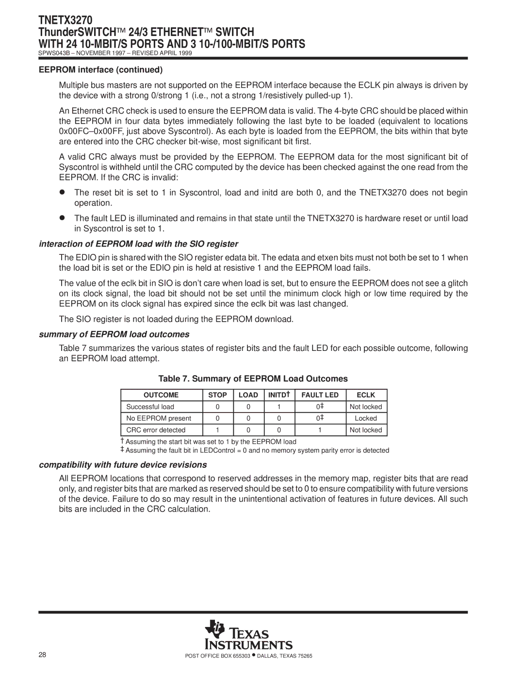
Table 7 summarizes the various states of register bits and the fault LED for each possible outcome, following an EEPROM load attempt.
Table 7. Summary of EEPROM Load Outcomes
OUTCOME | STOP | LOAD | INITD² | FAULT LED | ECLK |
Successful load | 0 | 0 | 1 | 0³ | Not locked |
No EEPROM present | 0 | 0 | 0 | 0³ | Locked |
CRC error detected | 1 | 0 | 0 | 1 | Not locked |
|
|
|
|
|
|
² Assuming the start bit was set to 1 by the EEPROM load
³ Assuming the fault bit in LEDControl = 0 and no memory system parity error is detected
compatibility with future device revisions
All EEPROM locations that correspond to reserved addresses in the memory map, register bits that are read only, and register bits that are marked as reserved should be set to 0 to ensure compatibility with future versions of the device. Failure to do so may result in the unintentional activation of features in future devices. All such bits are included in the CRC calculation.
28 | POST OFFICE BOX 655303 •DALLAS, TEXAS 75265 |