|
|
|
|
|
|
|
|
|
|
|
|
|
|
|
|
|
|
|
|
|
|
|
| TNETX3270 | |
|
|
|
|
|
|
|
|
|
|
|
|
|
|
|
|
|
|
|
| ThunderSWITCH 24/3 ETHERNET SWITCH | |||||
|
|
|
|
|
|
|
|
|
|
|
|
|
|
|
|
|
|
| WITH 24 | ||||||
|
|
|
|
|
|
|
|
|
|
|
|
|
|
|
|
|
|
|
|
|
|
| SPWS043B ± NOVEMBER 1997 ± REVISED APRIL 1999 | ||
|
|
|
|
|
|
|
|
|
|
|
|
|
|
|
|
|
|
|
|
|
|
|
|
|
|
|
|
|
|
|
|
|
|
|
|
|
|
|
|
|
|
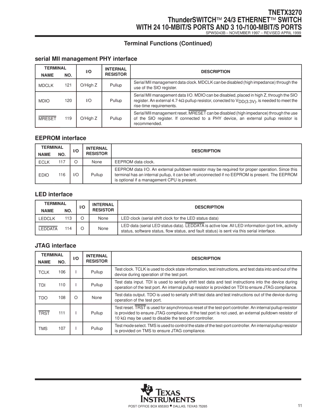
| Terminal Functions (Continued) | ||||||||
serial MII management PHY interface | |||||||||||||||||||||||||
|
|
|
|
|
|
|
|
|
|
|
|
|
|
|
|
|
|
|
|
|
|
|
|
| |
| TERMINAL |
|
|
|
| I/O |
| INTERNAL |
|
|
|
| DESCRIPTION |
| |||||||||||
| NAME |
| NO. |
|
|
|
|
| RESISTOR |
|
|
|
|
| |||||||||||
|
|
|
|
|
|
|
|
|
|
|
|
|
|
|
|
| |||||||||
|
|
|
|
|
|
|
|
|
|
|
|
|
|
|
|
|
|
|
|
|
|
|
|
|
|
| MDCLK | 121 |
|
| O/High Z |
|
| Pullup | Serial MII management data clock. MDCLK can be disabled (high impedance) through the |
| |||||||||||||||
|
|
|
|
| use of the SIO register. |
| |||||||||||||||||||
|
|
|
|
|
|
|
|
|
|
|
|
|
|
|
|
|
|
| |||||||
|
|
|
|
|
|
|
|
|
|
|
|
|
|
|
|
|
|
|
|
|
|
|
|
|
|
|
|
|
|
|
|
|
|
|
|
|
|
|
|
|
|
|
| Serial MII management data I/O. MDIO can be disabled, placed in high Z, through the SIO |
| ||||||
| MDIO | 120 |
|
|
|
| I/O |
|
| Pullup | register. An external |
| |||||||||||||
|
|
|
|
|
|
|
|
|
|
|
|
|
|
|
|
|
|
| |||||||
|
|
|
|
|
|
|
|
|
|
|
|
|
|
|
|
|
|
|
|
|
|
|
| ||
|
|
|
|
|
|
|
|
|
|
|
|
|
|
|
|
|
| Serial MII management reset. |
|
| can be disabled (high impedance) through the use |
| |||
|
|
|
|
|
|
|
|
|
|
|
|
|
|
|
|
|
| MRESET |
| ||||||
| MRESET |
| 119 |
|
| O/High Z |
|
| Pullup | of the SIO register. If connected to a PHY device, an external pullup resistor is |
| ||||||||||||||
|
|
|
|
|
|
|
|
|
|
|
|
|
|
|
|
|
| recommended. |
| ||||||
|
|
|
|
|
|
|
|
|
|
|
|
|
|
|
|
|
|
|
| ||||||
EEPROM interface |
|
|
|
|
|
|
|
|
|
|
|
| |||||||||||||
|
|
|
|
|
|
|
|
|
|
|
|
|
|
|
|
|
|
|
|
|
| ||||
| TERMINAL |
| I/O |
|
| INTERNAL |
|
|
|
|
|
|
| DESCRIPTION |
| ||||||||||
NAME | NO. |
|
|
| RESISTOR |
|
|
|
|
|
|
|
| ||||||||||||
|
|
|
|
|
|
|
|
|
|
|
|
|
|
|
| ||||||||||
|
|
|
|
|
|
|
|
|
|
|
|
|
|
|
|
|
|
| |||||||
| ECLK | 117 |
| O |
|
|
| None |
|
| EEPROM data clock. |
| |||||||||||||
|
|
|
|
|
|
|
|
|
|
|
|
|
|
|
|
|
|
|
|
|
|
| |||
|
|
|
|
|
|
|
|
|
|
|
|
|
|
|
| EEPROM data I/O. An external pulldown resistor may be required for proper operation. Since this |
| ||||||||
| EDIO | 116 |
| I/O |
|
|
| Pullup |
|
| terminal has an internal pullup, it can be left unconnected if no EEPROM is present. The EEPROM |
| |||||||||||||
|
|
|
|
|
|
|
|
|
|
|
|
|
|
|
| is optional if a management CPU is present. |
| ||||||||
|
|
|
|
|
|
|
|
|
|
|
|
|
|
|
|
|
|
|
|
|
|
| |||
LED interface |
|
|
|
|
|
|
|
|
|
|
|
|
|
|
|
|
|
|
| ||||||
|
|
|
|
|
|
|
|
|
|
|
|
|
|
|
|
|
|
| |||||||
| TERMINAL |
|
| I/O |
| INTERNAL |
|
|
|
|
| DESCRIPTION |
| ||||||||||||
| NAME |
| NO. |
|
|
| RESISTOR |
|
|
|
|
|
| ||||||||||||
|
|
|
|
|
|
|
|
|
|
|
|
|
|
|
| ||||||||||
|
|
|
|
|
|
|
|
|
|
|
|
|
|
|
|
| |||||||||
| LEDCLK | 113 |
|
| O |
| None |
|
| LED clock (serial shift clock for the LED status data) |
| ||||||||||||||
|
|
|
|
|
|
|
|
|
|
|
|
|
|
|
|
|
|
|
|
| |||||
|
|
|
|
|
|
|
|
|
|
|
|
|
|
|
|
| LED data (serial LED status data). |
|
| is active low. All LED information (port link, activity |
| ||||
|
|
|
| 114 |
|
| O |
| None |
|
| LEDDATA |
| ||||||||||||
| LEDDATA |
|
|
|
| ||||||||||||||||||||
|
|
|
|
|
| status, software status, flow status, and fault status) is sent via this serial interface. |
| ||||||||||||||||||
|
|
|
|
|
|
|
|
|
|
|
|
|
|
|
|
|
| ||||||||
|
|
|
|
|
|
|
|
|
|
|
|
|
|
|
|
|
|
|
| ||||||
JTAG interface |
|
|
|
|
|
|
|
|
|
|
|
|
|
|
|
|
| ||||||||
|
|
|
|
|
|
|
|
|
|
|
|
|
|
|
|
|
|
| |||||||
| TERMINAL |
| I/O |
|
| INTERNAL |
|
|
|
|
|
|
| DESCRIPTION |
| ||||||||||
NAME | NO. |
|
|
| RESISTOR |
|
|
|
|
|
|
|
| ||||||||||||
|
|
|
|
|
|
|
|
|
|
|
|
|
|
|
| ||||||||||
|
|
|
|
|
|
|
|
|
|
|
|
|
|
|
|
|
|
|
| ||||||
| TCLK | 106 |
| I |
|
|
| Pullup |
|
| Test clock. TCLK is used to clock state information, test instructions, and test data into and out of the |
| |||||||||||||
|
|
|
|
|
|
| device during operation of the test port. |
| |||||||||||||||||
|
|
|
|
|
|
|
|
|
|
|
|
|
|
|
|
| |||||||||
|
|
|
|
|
|
|
|
|
|
|
|
|
|
|
|
|
|
|
| ||||||
| TDI | 110 |
| I |
|
|
| Pullup |
|
| Test data input. TDI is used to serially shift test data and test instructions into the device during |
| |||||||||||||
|
|
|
|
|
|
| operation of the test port. An internal pullup resistor is provided on TDI to ensure JTAG compliance. |
| |||||||||||||||||
|
|
|
|
|
|
|
|
|
|
|
|
|
|
|
|
| |||||||||
|
|
|
|
|
|
|
|
|
|
|
|
|
|
|
|
|
|
|
| ||||||
| TDO | 108 |
| O |
|
|
| None |
|
| Test data output. TDO is used to serially shift test data and test instructions out of the device during |
| |||||||||||||
|
|
|
|
|
|
| operation of the test port. |
| |||||||||||||||||
|
|
|
|
|
|
|
|
|
|
|
|
|
|
|
|
| |||||||||
|
|
|
|
|
|
|
|
|
|
|
|
|
|
|
|
|
| ||||||||
|
|
|
|
|
|
|
|
|
|
|
|
|
|
|
| Test reset. |
| is used for asynchronous reset of the |
| ||||||
|
|
|
|
|
|
|
|
|
|
|
|
|
|
|
| TRST |
| ||||||||
| TRST |
| 111 |
| I |
|
|
| Pullup |
|
| is provided to ensure JTAG compliance. If the test port is not used, an external pulldown resistor of |
| ||||||||||||
|
|
|
|
|
|
|
|
|
|
|
|
|
|
|
| 10 kΩ may be used to disable the |
| ||||||||
|
|
|
|
|
|
|
|
|
|
|
|
|
|
|
|
|
| ||||||||
| TMS | 107 |
| I |
|
|
| Pullup |
|
| Test mode select. TMS is used to control the state of the |
| |||||||||||||
|
|
|
|
|
|
| is provided on TMS to ensure JTAG compliance. |
| |||||||||||||||||
|
|
|
|
|
|
|
|
|
|
|
|
|
|
|
|
| |||||||||
|
|
|
|
|
|
|
|
|
|
|
|
|
|
|
|
|
|
|
|
|
|
|
|
|
|
POST OFFICE BOX 655303 •DALLAS, TEXAS 75265 | 11 |