INDOOR UNIT
OUTDOOR UNIT
DIGITAL INVERTER
<SUPER DIGITAL INVERTER>
CONTENTS
SAFETY CAUTION
SPECIFICATIONS
WIRING DIAGRAM
6. REFRIGERANT R410A
7. INDOOR CONTROL CIRCUIT
SAFETY CAUTION
DANGER
Explanation of indications
Explanation of illustrated marks
– 5 –
– 6 –
1. Safety Caution Concerned to New Refrigerant
2.Cautions on Installation/Service
• New Refrigerant R410A
3.Pipe Materials
General tools Conventional tools can be used
4.Tools
– 8 –
1. SPECIFICATIONS
1-1.Indoor Unit
1-1-1. 4-WayAir Discharge Cassette Type
– 9 –
– 10 –
Model
Indoor unit
SM564UT-E
– 11 –
<Twin type>
Page
– 13 –
1-1-2.Concealed Duct Type <Single type>
– 14 –
Twin type
– 15 –
1-1-3.Under Ceiling Type <Single type>
– 16 –
Twin type
– 17 –
1-1-4.High Wall Type <Single type>
– 18 –
<Twin type>
– 19 –
Model
Indoor unit
RAV-SM562MUT-E
– 20 –
<Twin type>
Indoor unit
SM562MUT-E
1-2.Outdoor Unit
<Super Digital Inverter>
1-3.Operation Characteristic Curve
– 22 –
– 23 –
2-1.Indoor Unit
RAV-SM564UT-E
– 24 –
RAV-SM804UT-E
– 25 –
RAV-SM1104UT-E, RAV-SM1404UT-E
2-2.Outdoor Unit
– 26 –
– 27 –
RAV-TWP30E2, RAV-TWP50E2Simultaneous Twin
3. SYSTEMATIC REFRIGERATING CYCLE DIAGRAM
3-1.Indoor Unit
3-2.Outdoor Unit
3-3.Systematic Diagram of Refrigerating Cycle
– 29 –
RAV-SP1104AT-E, RAV-SP1104ATZ-E, RAV-SP1104ATZG-E
4. WIRING DIAGRAM
4-1.Indoor Unit
Control P.C. Board
for Indoor Unit
Control P.C. Board MCC-1570
4-2.Outdoor Unit Wiring Diagram
Color Identification
– 31 –
5. SPECIFICATIONS OF ELECTRICAL PARTS
5-3.Accessory Separate Sold Parts
5-1.Indoor Unit
5-2.Outdoor Unit Parts Ratings
6-1.Safety During Installation/Servicing
6-2.Refrigerant Piping Installation
6. REFRIGERANT R410A
6-2-1.Piping Materials and Joints Used
6-2-2.Processing of Piping Materials
– 34 –
Table 6-2-1Thicknesses of annealed copper pipes
Thickness mm
Fig. 6-2-1Flare processing dimensions
Flare and flare nut dimensions for R410A
Flare and flare nut dimensions for R22
– 35 –
– 36 –
Nominal
Outer diameter
Tightening torque
6-3.Tools
6-4.Recharging of Refrigerant
Fig. 6-4-1Configuration of refrigerant charging
6-3-1.Required Tools
6-5.Brazing of Pipes
3.Low temperature brazing filler
6-5-2.Flux 1.Reason why flux is necessary
6-5-1.Materials for Brazing
2.Characteristics required for flux
3.Types of flux •Noncorrosive flux
•Activated flux
6-5-3.Brazing
6-6.Instructions for Re-usePiping of R22 or R407C
6-6-4.Curing of Pipes
6-6-5.Final Installation Checks
– 41 –
DANGER
Cautions for using existing pipe
6-6-6.Handling of Existing Pipe
Operation method
7-1.Indoor Controller Block Diagram
7-1-1.Connection of Main Sub Remote Controller
Weekly timer
7. INDOOR CONTROL CIRCUIT
Indoor unit #1 Master
– 44 –
Case of TCC-LINKadapter
Wireless remote controller kit
Main sub master remote controller
Weekly timer
– 45 –
7-2.Control Specifications
Outline of specifications
– 46 –
Item
Item
Outline of specifications
Remarks
Outline of specifications
– 48 –
Remarks
<COOL>
Outline of specifications
– 49 –
Item
Remarks
Outline of specifications
– 50 –
Item
Remarks
Outline of specifications
Setup at shipment
– 51 –
Item
Outline of specifications
<<Individual air direction setup>>
– 52 –
Remarks
Outline of specifications
– 53 –
Item
12Louver control <<Selection of Swing mode>>
Outline of specifications
– 54 –
Item
Remarks
Outline of specifications
– 55 –
Item
Remarks
Outline of specifications
– 56 –
Item
Remarks
Outline of specifications
– 57 –
Item
Remarks
– 58 –
∗This option is not provided to oversea models
7-4.Indoor
Print Circuit Board
– 59 –
<MCC-1570>
8-1.Outdoor Controls
8-1-1.Print Circuit Board
– 60 –
Viewed from parts of P.C board
2.Discharge temperature release control
8-2.Outline of Main Controls
1.PMV Pulse Motor Valve control
REQUIREMENT
3. Outdoor fan control
3-1Cooling fan control
3-2Heating fan control
– 62 –
4.Coil heating control
5.Short intermittent operation preventive control
6.Current release control
REQUIREMENT
7.Current release value shift control
8.Over-currentprotective control
9.High-pressurerelease control
– 64 –
10.Defrost control
Start of heating operation
9. TROUBLESHOOTING
9-1.Summary of Troubleshooting
1.Before troubleshooting
2. Troubleshooting procedure
2.Troubleshooting procedure
1.Before troubleshooting
<Wireless remote controller type>
– 67 –
9-2.Troubleshooting
9-2-1.Outline of judgment
Page
9-2-2.Others Other than Check Code
– 70 –
Page
Check Code List Outdoor
– 73 –
Error mode detected by indoor unit
– 74 –
– 75 –
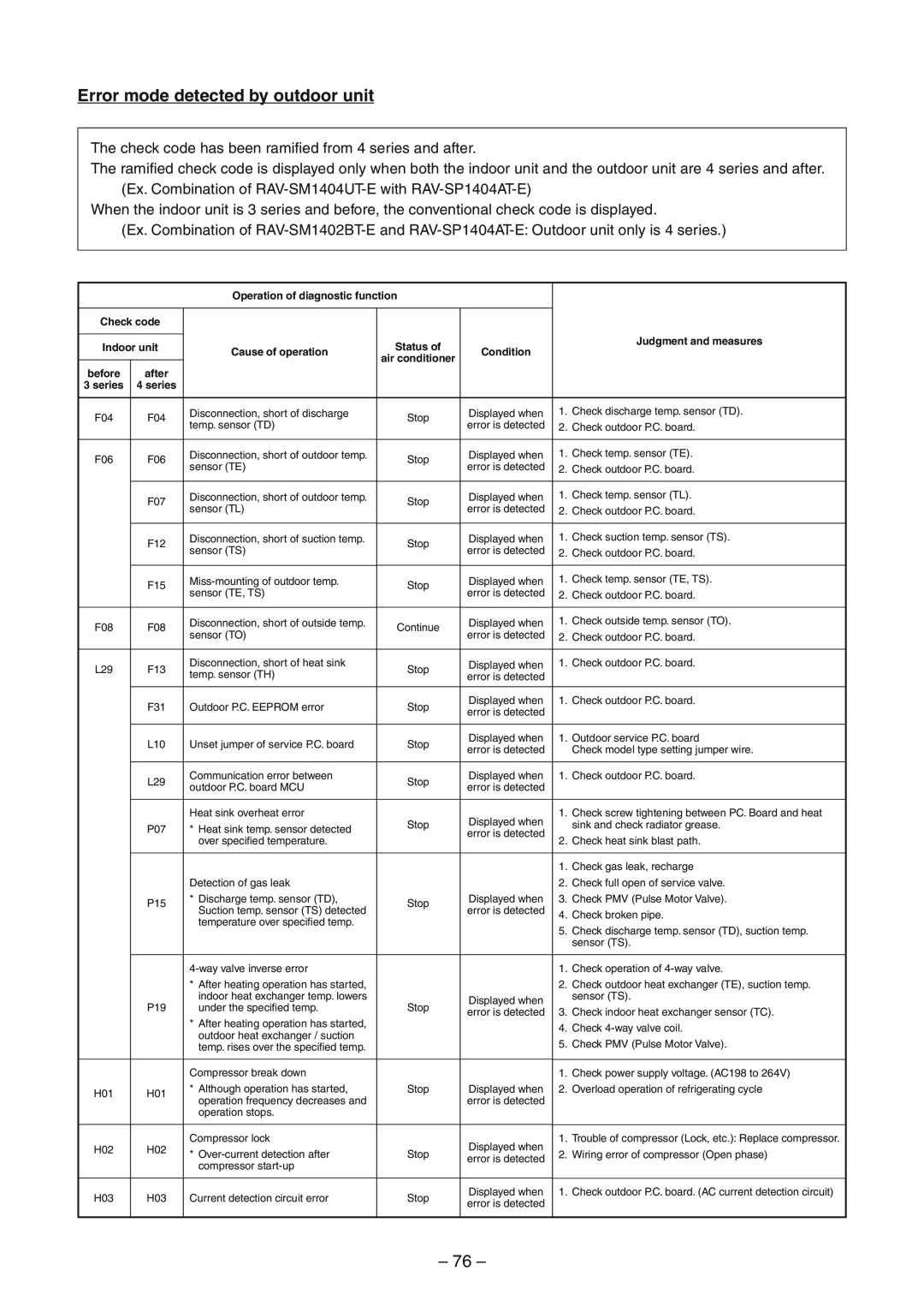
Error mode detected by outdoor unit
– 76 –
– 77 –
E09 error
Check code E01 error
– 78 –
E10 error
E04 error
– 79 –
E18 error
E08, L03, L07, L08 error
L09 error
– 80 –
L20 error
L30 error
P30 error Central controller
– 81 –
P10 error
F10 error
P12 error
– 83 –
F01 error
F02 error
– 84 –
C06 error TCC-LINKcentral controller
E03 error Master indoor unit
F29 error
P31 error Follower indoor unit
– 86 –
Dip switch setup
<Latest error display>
<Error display, which occurs at present
LED display on outdoor P.C. board
ll ¡l
– 89 –
– 90 –
– 91 –
– 92 –
Page
– 94 –
– 95 –
Check and troubleshooting
Check
Outdoor
code
l¥ ¡¥
Temperature sensor
TA, TC, TCJ,TE, TS, TO sensors
TD, TL sensors
TA, TC, TCJ,TE, TS, TO sensors
10. REPLACEMENT OF SERVICE P.C. BOARD
<Replacement procedures>
CASE
10-1.Indoort Unit
– 100 –
1 Setting data read out from EEPROM
CODE No. required at least
3 Writing the setting data to EEPROM
3 6 5
101
<Fig. 1 RBC-AMT32E>
– 102 –
<Fig. 2 EEPROM layout diagram>
<Fig. 2>
Table 1. Setting data CODE No. table example
– 103 –
Table 2. Type: CODE No.
Table 3. Indoor unit capacity CODE No.
Page
11. SETUP AT LOCAL SITE AND OTHERS
3 4 5
11-1.Indoor Unit
11-1-1.Test Run Setup on Remote Controller
conditioner from the wireless remote controller
1 Turn off power of the air conditioner
Turn off power of the air conditioner
– 106 –
<In case of wireless remote controller>
4, 5,
– 107 –
1.D501 Red
2.D403 Red
3.D503 Yellow: Main bus communication
4.D504 Green: Sub bus communication
3 4 5 6
3 6 1
4 5 2
1 2 3 4 5 6 END
Contents
– 110 –
Function selection item No. DN list
Item
Contents
– 111 –
Item
At shipment from factory
<Wired remote controller>
<Wireless remote controller>
Setup method
– 112 –
2 4 1
nCalling of sensor temperature display <Contents>
<Procedure>
call the service monitor mode
nCalling of error history Contents
<Procedure>
4 seconds or more to call the service check mode
REQUIREMENT
nIndoor unit power-ONsequence
– 115 –
11-2.Setup at Local Site / Others
2. Microprocessor block diagram
3.TCC-LINKwiring connection
1. Function
4. Wiring specifications
5. P.C. board switch SW01 setup
– 117 –
Size
6. External view of P.C. board assembly
7. Address setup
11-3.How to Set up Central Control Address Number
1 2 3
– 119 –
1 Push UNIT LOUVER button for 4 seconds or more
3. How to set up type of swing
4 Push SET 5 Push TEST to finish the setup
REQUIREMENT
– 120 –
4. How to set louver lock Louver fix
5. How to clear louver lock
6. How to set contents of save operation
NOTIFICATION
11-4.Outdoor Unit
Operation method
11-4-1.Refrigerant Recovery Control
122
1. Outline
– 123 –
Operation part
Display part
11-4-4.Others
1.Selection of LED display SW800, SW803 operation
– 124 –
1Display selection list
lllll¡
lllll¡ ¡llll¡ l¡lll¡
Specific operation
– 127 –
SW804
– 128 –
SW804
12. ADDRESS SETUP
12-1.Address Setup
<Address setup procedure>
– 129 –
12-2.Address Setup & Group Control
12-2-1.System configuration
– 130 –
<Terminology>
– 131 –
1. Standard One outdoor unit
1 Single
2 Gr operation
10 11
2, 5,
3, 6, 9 4, 7,
1 2 3 4 5 6 7 8 9 10 11 END
1 2 END
1 2 3 END
<Procedure>
<Procedure>
<Maintenance/Check list>
– 134 –
13. DETACHMENTS
13-1.Indoor Unit
13-1-1. 4-WayAir Discharge Cassette Type
– 135 –
Procedure
– 136 –
2.Attachment
Part name
Procedure
– 137 –
2. Attachment
No. Part name
Procedure
– 138 –
1. Detachment
2.Attachment
Procedure
– 139 –
†Drain cap 1. Detachment
2. Attachment
Procedure
– 140 –
‡Fan motor 1. Detachment
2. Attachment
Procedure
– 141 –
‡Fan motor 2. Attachment
No. Part name
Procedure
– 142 –
ˆDrain pump 1. Detachment
2. Attachment
Procedure
– 143 –
2.Attachment
ŠDrain pan 1. Detachment
Procedure
– 144 –
1. Detachment
2. Attachment
13-2.Outdoor Unit
XREQUIREMENTX
– 145 –
XCAUTIONX
Procedure
– 146 –
‚Discharge 1. Detachment
No. Part name
„Replacement of 1. Control P.C. board
Procedure
– 147 –
No. Part name
– 148 –
Procedure
No. Part name
Procedure
XREQUIREMENTX
– 149 –
No. Part name
– 150 –
†Compressor 1. Removal of defective compressor
No. Part name
Remarks
Procedure
– 151 –
†Compressor 2. Mounting of compressor
3. Vacuuming
Procedure
REQUIREMENT
REQUIREMENT
– 152 –
14. EXPLODED VIEWS AND PARTS LIST
14-1.Indoor Unit
– 154 –
Location
Part No
Description
– 155 –
Location
Description
Model Name
308,
– 157 –
RBC-AX31U W-E, RBC-AX31U WS-E
Location
Part No
14-2.Outdoor Unit
– 159 –
709,
WARNINGS ON REFRIGERANT LEAKAGE
Check of Concentration Limit
TOSHIBA CARRIER CORPORATION