AIR-CONDITIONER
Contents
104
10-1
10-2
11-1
Confirmation of warning label on the main unit
Explanation of indications
Explanation of illustrated marks
Indication Explanation
Catch the inner wires
∗ For details, refer to the parts list
Never recover the refrigerant into the outdoor unit
Do not modify the products
Side
Check the following items after reinstallation
Metal section Earth position
Limit even if the refrigerant leaks
Copper pipe Piping
Safety Caution Concerned to New Refrigerant
Pipe Materials
Flare nut
R410A Conventional air
Air conditioner installation Conditioner installation
General tools Conventional tools can be used
Used tool Usage
Single type
Indoor Unit
Way Air Discharge Cassette Type
Model Indoor unit
RAV SM564UT-E SM804UT-E
SM1104UT-E SM1404UT-E Outdoor unit
Twin type
SP1104ATZZG-E SP1404ATZZG-E
SM1103AT-E SM1403AT-E
Concealed Duct Type Single type
562BT-E 802BT-E 1102BT-E 1402BT-E Outdoor unit
RAV SM562BT-E SM802BT-E
Under Ceiling Type Single type
562CT-E 802CT-E 1102CT-E 1402CT-E Outdoor unit
SM562CT-E SM802CT-E
SP1104ATZZG-E SP1404AZZG-E
High Wall Type Single type
RAV SM562KRT-E SM802KRT-E
SM562KRT-E SM802KRT-E
Compact 4-Way Cassette 600 × 600 Type Single type
RAV-SM562MUT-E
SP1104ZZG-E
802ATZZG-E 1104ATZZG-E
Super Digital Inverter
Model name Outdoor unit
Cooling Heating RAV-SP1404 RAV-SP1104
Operation characteristic curve Super Digital Inverter
Capacity variation ratio according to temperature
Cooling Heating
RAV-SM564UT-E
RAV-SM804UT-E
RAV-SM1104UT-E, RAV-SM1404UT-E
Name
Details of a
RAV-TWP30E2, RAV-TWP50E2 Simultaneous Twin
Model RBC
Single type Combination of 1 indoor unit and 1 outdoor unit
Twin type Combination of 2 indoor units and 1 outdoor unit
RAV-SP1104AT-E, RAV-SP1104ATZ-E, RAV-SP1104ATZG-E
MCC-1570
Control P.C. Board
For Indoor Unit
Color
Symbol Parts name
Color Identification
Parts name Type Specifications
RBC-U31PGWS-E, RBC-U31PGW-E Ceiling panel
Safety During Installation/Servicing
Piping Materials and Joints Used
Outer diameter mm R410A R22
Processing of Piping Materials
1 Thicknesses of annealed copper pipes Thickness mm
Minimum thicknesses of socket joints
Outer Thickness Nominal Conventional flare tool
Flare and flare nut dimensions for R410A
Flare and flare nut dimensions for R22
Flare tool for
Nm kgfm
Wrenches available on the market
1 Configuration of refrigerant charging
Required Tools
Materials for Brazing Silver brazing filler
Low temperature brazing filler
Flux Reason why flux is necessary
Phosphor bronze brazing filler
Activated flux
Characteristics required for flux
Types of flux Noncorrosive flux
Piping materials for brazing and used brazing filler/flux
Curing of Pipes
Basic Conditions Need to Reuse the Existing Pipe
Branching Pipe for Simultaneous Operation System
Restricted Items to Use the Existing Pipes
Final Installation Checks
Existing pipe SW Switch
Operation method
When using existing pipe
Handling of Existing Pipe
Reference outside diameter Wall thickness
Indoor Controller Block Diagram
Connection of Main Sub Remote Controller
Connection of Wireless Remote Controller Kit
Wireless remote controller kit
Max units
Outline of specifications Remarks
Control outline Command
Setup data
Cool
Air speed
Conditions
Setup at shipment
Control temp. C
All operations
Individual air direction setup
Cooling/dry operation Heating/fan operation
Dual swing
Outline of specifications
Louver control Selection of Swing mode
Louver lock Louver fix
Selection of horizontal discharge position
Control which ignores lock Objective louver No
Filter
FAN
Louver
Mode
Function Connector No Pin No Specifications
Remarks
MCC-1570
Indoor
Print Circuit Board
Viewed from parts of P.C board
Outdoor Controls
Print Circuit Board
MCC-1571
Discharge temperature release control
Outline of Main Controls PMV Pulse Motor Valve control
Heating fan control
Outdoor fan control
Cooling fan control
Current release control
Coil heating control
Short intermittent operation preventive control
Over-current protective control
Temperature range SP110, SP140
Current release value shift control
High-pressure release control
Normal To Abnormal To
Defrost control
Start of heating operation
J805 J806
Troubleshooting procedure
Summary of Troubleshooting
Before troubleshooting
Wired remote controller type
Wireless remote controller type
Trouble Confirmation of lamp display
Lamp indication Check code Cause of trouble occurrence
Troubleshooting
Outline of judgment
Ready
Cause of trouble occurrence
Others Other than Check Code
Lamp indication Check code
Indoor unit detected
Check Code List Indoor
Remote controller detected
Central control devices detected
Check Code List Outdoor
Way valve inverse error
Indoor unit Heat exchanger sensor TCJ error
Error mode detected by indoor unit
Cause of operation Status
Cause of operation
Error mode detected by outdoor unit
Series
Operation of diagnostic function
E09 error
E04 error
E10 error
L09 error
E18 error
E08, L03, L07, L08 error
P30 error Central controller
L20 error
L30 error
P10 error
F10 error
P12 error
CN333 CN334
F02 error
F01 error
C06 error TCC-LINK central controller
P31 error Follower indoor unit
E03 error Master indoor unit
F29 error
Latest error display
Diagnostic Procedure for Each Check Code Outdoor Unit
LED display on outdoor P.C. board Dip switch setup
Error display, which occurs at present
Display Display 2 Heat exchanger temp. sensor TE error
F06
F31 Display Eeprom error
F12 Display 1 Display 2 Suction temp. sensor TS error
F13 Display Display 2 Heat sink temp. sensor TH error
H03 Display 1 Display 2 Current detection circuit error
H02 Display Compressor lock
L10 Display
Display Communication error between MCU
Is PMV Normal?
P05 Display Display 2 Power supply error Voltage error
Is refrigerant charge amount adequate? Recharge refrigerant
Replace defective part
P15 Display 1 Display 2 Gas leak detection
Exchange to cooling cycle Exchange to heating cycle
Loosening of outdoor fan?
P29
Position detection circuit error
Single operation check for outdoor fan
TA, TC, TCJ,TE, TS, to sensors
Temperature sensor
Temperature Resistance value characteristic table
TD, TL sensors
Replacement procedures
Indoort Unit
Contents
Setting data read out from Eeprom
C. Board for indoor unit servicing replacement procedures
100
101
Writing the setting data to Eeprom
Jumper wire J02
Eeprom layout diagram
102
Type Code No
Setting data Code No. table example
103
Indoor unit capacity Code No
Model switching J800 to J803
Outdoor Unit Setting the jumper wires and DIP switches
Installing the P.C. board
104
105
Test Run Setup on Remote Controller
Wired remote controller
Push
Return Dip switch of the sensor section as before
Use either Cool or Heat operation mode for test operation
Conditioner from the wireless remote controller
106
107
Case of wireless remote controller
Procedure Description
Test cooling operation Test heating operation
D503 Yellow Main bus communication
D501 Red
D403 Red
D504 Green Sub bus communication
Push button. OK if indication lights
Function Selection Setup
109
Pushing button returns the status to the normal stop status
110
Function selection item No. DN list
111
Setup method
Wiring and Setting of Remote Controller Control
When connected 2 remote controllers operate the twin
112
Monitor Function of Remote Controller Switch
113
114
By feed unit Automatic address judgment
Indoor unit power-ON sequence
115
Initial communication
TCC-LINK wiring connection
Setup at Local Site / Others
Microprocessor block diagram
Function
No. of wires
Wiring specifications
C. board switch SW01 setup
117
How to Set up Central Control Address Number
External view of P.C. board assembly
Address setup
Setup from remote controller at indoor unit side
119
Push SET Push Test to finish the setup
How to set up type of swing
Using Timer SET / buttons, select type of the swing
Swing setup code Louver operation
How to set contents of save operation
How to set louver lock Louver fix
How to clear louver lock
122
Refrigerant Recovery Control
Operation method
123
Service Support Function LED Display, Switch Operation
Outline
Operation part
124
Switch Function / Contents Refer
Others Selection of LED display SW800, SW803 operation
Display selection list
125
Error display
Error contents
126
127
Specific operation for maintenance check SW801, SW804
Operation when pushdown button switch SW801 is pushed
Specific operation
SW804 Operation when pushdown button switch SW801 is pushed
128
129
Address setup procedure
Item code Data at shipment Setup data range
130
Address Setup & Group Control
System configuration
Terminology
131
Only turning on source power supply Automatic completion
Automatic address example from unset address No miscabling
Manual setting from remote controller
132
Push Unit button
Procedure Push
133
To know the position of indoor unit body by address
Maintenance/Check list
134
Detachment
Procedure Remarks
135
Attachment
Part name Procedure
136
No. Part name Procedure
137
138
139
† Drain cap 1. Detachment
140
‡ Fan motor 1. Detachment
141
‡ Fan motor 2. Attachment
142
Drain pump 1. Detachment
143
Drain pan 1. Detachment
144
Procedure
145
146
‚ Discharge 1. Detachment
„ Replacement of 1. Control P.C. board
147
148
No. Part name Procedure Remarks
149
150
† Compressor 1. Removal of defective compressor
Vacuuming
151
† Compressor 2. Mounting of compressor
Refrigerant charge
Fan guard 1. Detachment
152
‡ PMV coil 1. Detachment
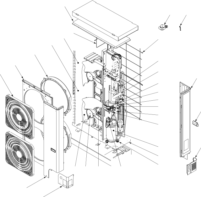
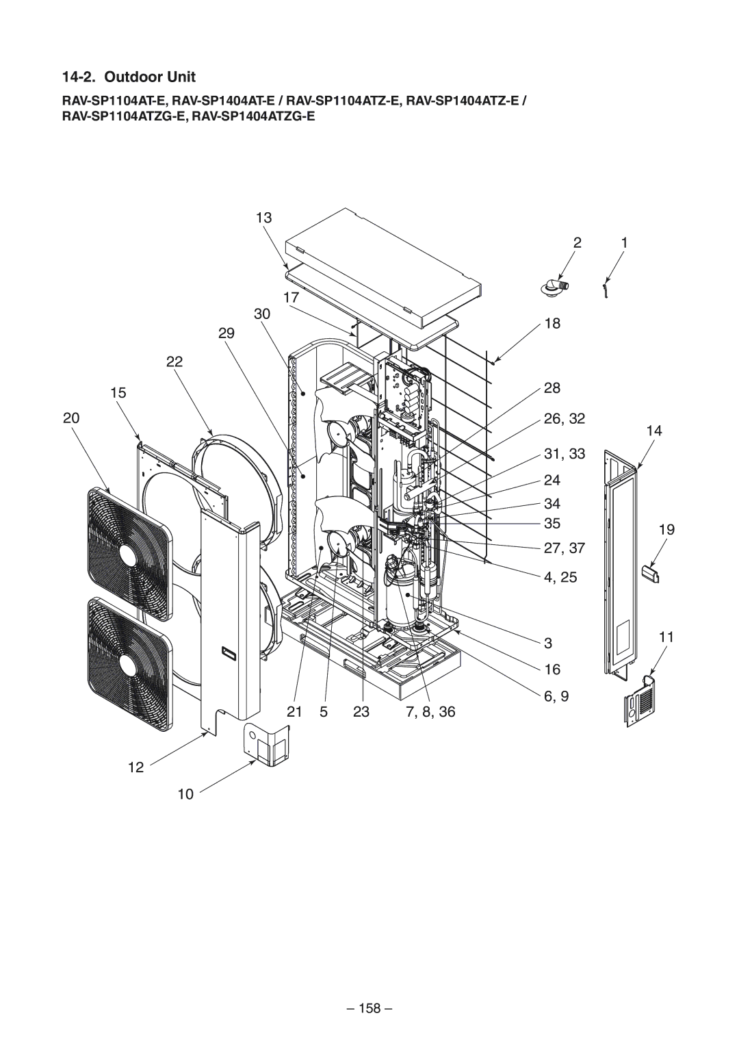
Exploded Views and Parts List
153
804UT-E 1104UT-E 1404UT-E
154
Location Description Model Name
564UT-E
403 404 405 401 402
155
156
303
319
U31PG W-E
157
AX31U W-E AX31U WS-E
16 6
158
1104ATZ-E 1404ATZ-E 1104ATZG-E 1404ATZG-E
159
Location Description Model Name
1104AT-E 1404AT-E 1104ATZ-E 1404ATZ-E 1104ATZG-E 1404ATZG-E
160
Description Model Name
Check of Concentration Limit
Toshiba Carrier Corporation