Chapter 1: SP605 Evaluation Board
10. SFP Module Connector
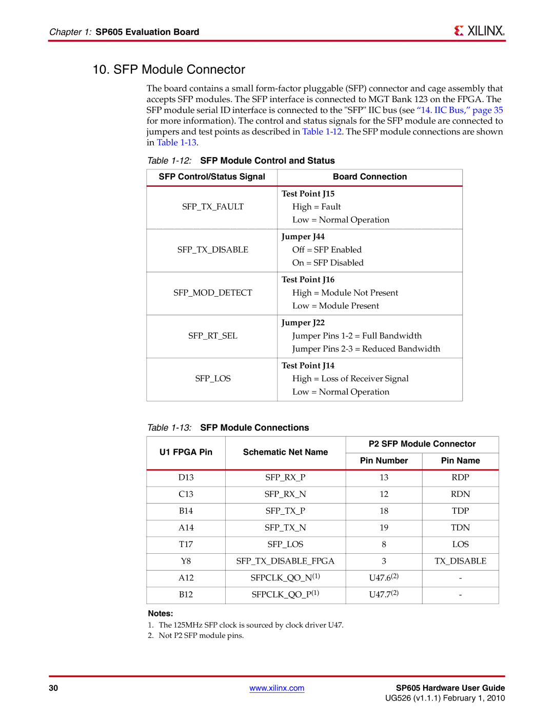
The board contains a small
Table
SFP Control/Status Signal | Board Connection |
|
|
| Test Point J15 |
SFP_TX_FAULT | High = Fault |
| Low = Normal Operation |
|
|
| Jumper J44 |
SFP_TX_DISABLE | Off = SFP Enabled |
| On = SFP Disabled |
|
|
| Test Point J16 |
SFP_MOD_DETECT | High = Module Not Present |
| Low = Module Present |
|
|
| Jumper J22 |
SFP_RT_SEL | Jumper Pins |
| Jumper Pins |
|
|
| Test Point J14 |
SFP_LOS | High = Loss of Receiver Signal |
| Low = Normal Operation |
|
|
Table
U1 FPGA Pin | Schematic Net Name | P2 SFP Module Connector | ||
|
| |||
Pin Number | Pin Name | |||
|
| |||
|
|
|
| |
D13 | SFP_RX_P | 13 | RDP | |
|
|
|
| |
C13 | SFP_RX_N | 12 | RDN | |
|
|
|
| |
B14 | SFP_TX_P | 18 | TDP | |
|
|
|
| |
A14 | SFP_TX_N | 19 | TDN | |
|
|
|
| |
T17 | SFP_LOS | 8 | LOS | |
|
|
|
| |
Y8 | SFP_TX_DISABLE_FPGA | 3 | TX_DISABLE | |
|
|
|
| |
A12 | SFPCLK_QO_N(1) | U47.6(2) | - | |
B12 | SFPCLK_QO_P(1) | U47.7(2) | - | |
Notes:
1.The 125MHz SFP clock is sourced by clock driver U47.
2.Not P2 SFP module pins.
30 | www.xilinx.com | SP605 Hardware User Guide |
|
| UG526 (v1.1.1) February 1, 2010 |