Chapter 1: SP605 Evaluation Board
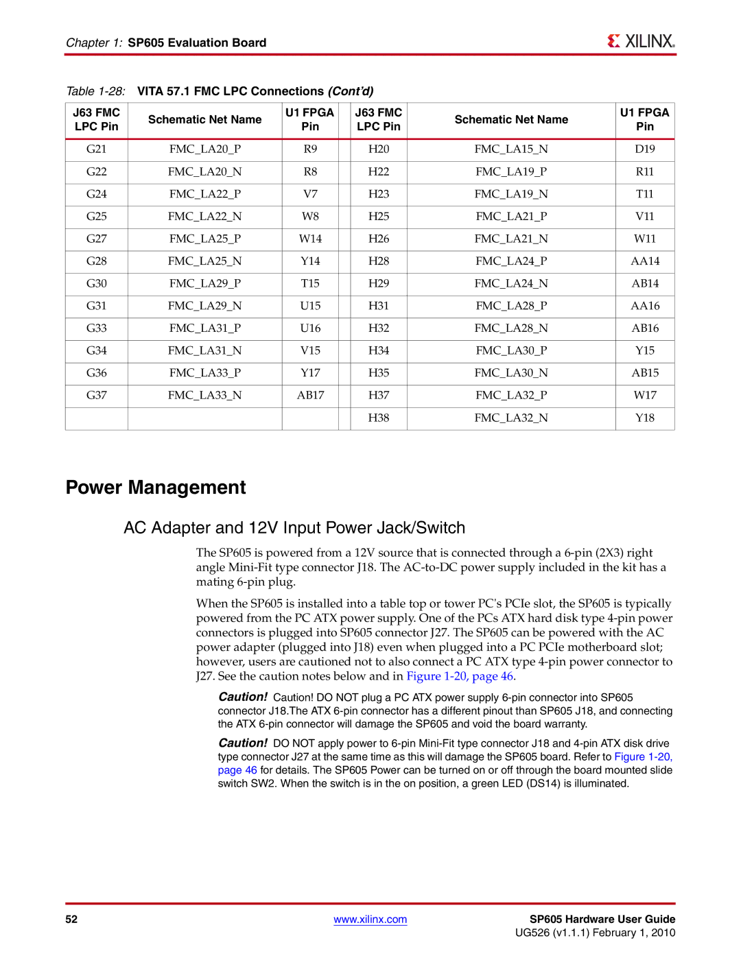
Table
J63 FMC | Schematic Net Name | U1 FPGA |
| J63 FMC | Schematic Net Name | U1 FPGA |
LPC Pin | Pin |
| LPC Pin | Pin | ||
|
|
| ||||
|
|
|
|
|
|
|
G21 | FMC_LA20_P | R9 |
| H20 | FMC_LA15_N | D19 |
|
|
|
|
|
|
|
G22 | FMC_LA20_N | R8 |
| H22 | FMC_LA19_P | R11 |
|
|
|
|
|
|
|
G24 | FMC_LA22_P | V7 |
| H23 | FMC_LA19_N | T11 |
|
|
|
|
|
|
|
G25 | FMC_LA22_N | W8 |
| H25 | FMC_LA21_P | V11 |
|
|
|
|
|
|
|
G27 | FMC_LA25_P | W14 |
| H26 | FMC_LA21_N | W11 |
|
|
|
|
|
|
|
G28 | FMC_LA25_N | Y14 |
| H28 | FMC_LA24_P | AA14 |
|
|
|
|
|
|
|
G30 | FMC_LA29_P | T15 |
| H29 | FMC_LA24_N | AB14 |
|
|
|
|
|
|
|
G31 | FMC_LA29_N | U15 |
| H31 | FMC_LA28_P | AA16 |
|
|
|
|
|
|
|
G33 | FMC_LA31_P | U16 |
| H32 | FMC_LA28_N | AB16 |
|
|
|
|
|
|
|
G34 | FMC_LA31_N | V15 |
| H34 | FMC_LA30_P | Y15 |
|
|
|
|
|
|
|
G36 | FMC_LA33_P | Y17 |
| H35 | FMC_LA30_N | AB15 |
|
|
|
|
|
|
|
G37 | FMC_LA33_N | AB17 |
| H37 | FMC_LA32_P | W17 |
|
|
|
|
|
|
|
|
|
|
| H38 | FMC_LA32_N | Y18 |
|
|
|
|
|
|
|
Power Management
AC Adapter and 12V Input Power Jack/Switch
The SP605 is powered from a 12V source that is connected through a
When the SP605 is installed into a table top or tower PC's PCIe slot, the SP605 is typically powered from the PC ATX power supply. One of the PCs ATX hard disk type
Caution! Caution! DO NOT plug a PC ATX power supply
Caution! DO NOT apply power to
52 | www.xilinx.com | SP605 Hardware User Guide |
|
| UG526 (v1.1.1) February 1, 2010 |