Chapter 1: SP605 Evaluation Board
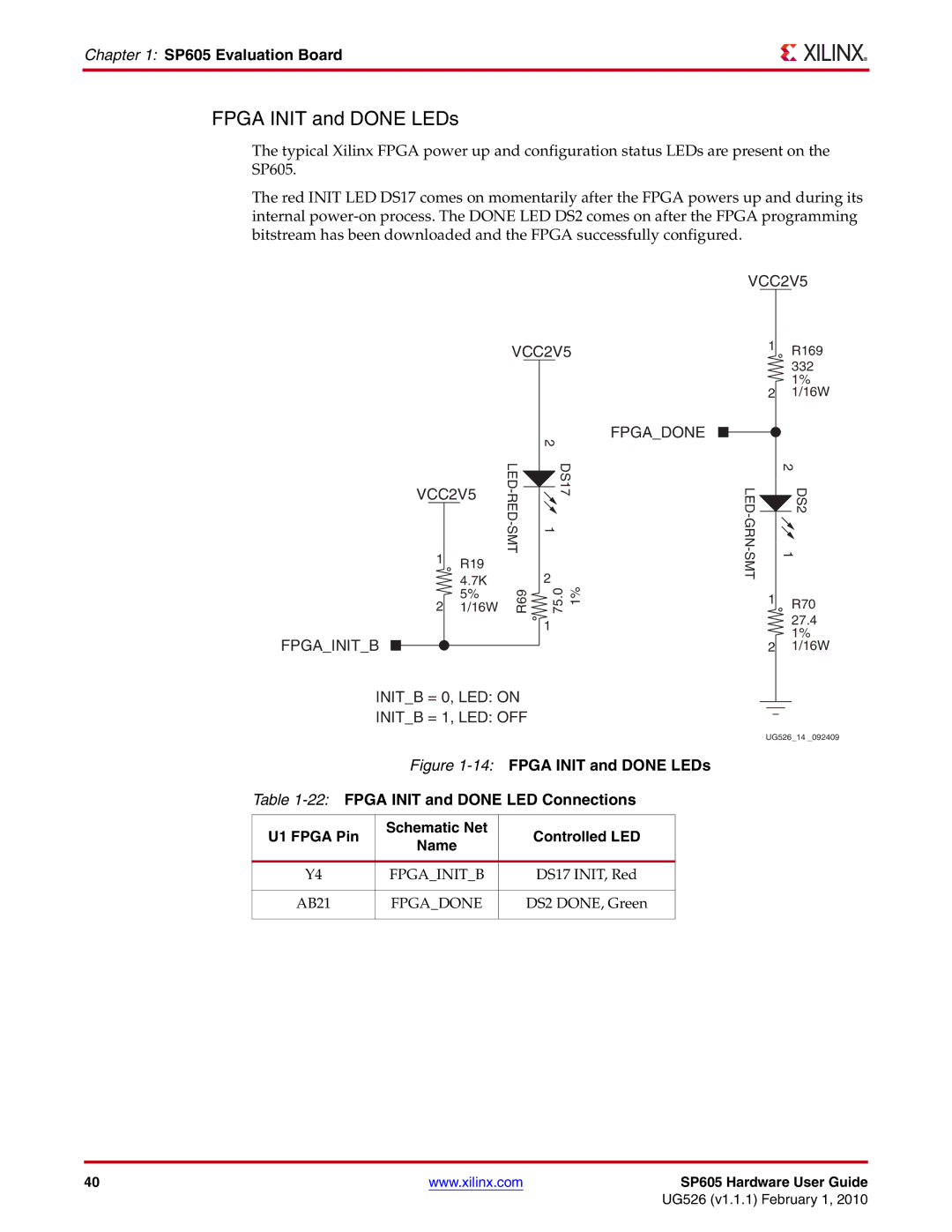
FPGA INIT and DONE LEDs
The typical Xilinx FPGA power up and configuration status LEDs are present on the SP605.
The red INIT LED DS17 comes on momentarily after the FPGA powers up and during its internal
VCC2V5
VCC2V5 | 1 | R169 |
|
332
1%
2 1/16W
FPGA_INIT_B
VCC2V5
1R19
4.7K
5%
21/16W
FPGA_DONE
| 2 |
|
DS17 |
| |
1 |
| |
MT |
|
|
| 2 | 1% |
R69 | 75.0 | |
| 1 |
|
|
|
| 2 |
| LED- |
| |
|
| ||
|
| DS2 | |
| 1 | ||
|
|
| |
|
|
|
|
1R70
27.4
1%
21/16W
| INIT_B = 0, LED: ON |
|
|
|
|
|
|
|
| |
|
|
|
|
|
|
|
|
| ||
| INIT_B = 1, LED: OFF |
|
|
|
| |||||
|
|
|
|
|
| |||||
|
|
|
|
| UG526_14 _092409 | |||||
| Figure | |||||||||
Table | ||||||||||
|
|
|
|
|
|
|
|
|
|
|
U1 FPGA Pin | Schematic Net |
| Controlled LED |
|
|
|
|
|
|
|
Name |
|
|
|
|
|
|
|
| ||
|
|
|
|
|
|
|
|
|
| |
|
|
|
|
|
|
|
|
|
|
|
Y4 | FPGA_INIT_B |
| DS17 INIT, Red |
|
|
|
|
|
|
|
|
|
|
|
|
|
|
|
|
|
|
AB21 | FPGA_DONE |
| DS2 DONE, Green |
|
|
|
|
|
|
|
|
|
|
|
|
|
|
|
|
|
|
40 | www.xilinx.com | SP605 Hardware User Guide |
|
| UG526 (v1.1.1) February 1, 2010 |