Chapter 1: SP605 Evaluation Board
17. Switches
The SP605 Evaluation board includes the following switches:
•Power On/Off Slide Switch SW2
•FPGA_PROG_B Pushbutton SW3
•SYSACE_RESET_B Pushbutton SW9
•System ACE CF CompactFlash Image Select DIP Switch S1
•Mode DIP Switch SW1
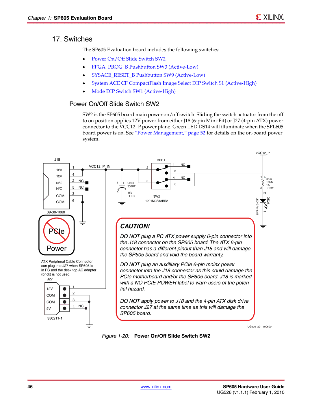
Power On/Off Slide Switch SW2
SW2 is the SP605 board main power on/off switch. Sliding the switch actuator from the off to on position applies 12V power from either J18
VCC12_P
J18 | DPDT |
|
| 1 |
|
|
| VCC12_P_IN |
|
| 1 | NC |
|
| ||
12v |
|
|
|
|
|
| 2 | 3 |
|
|
| |||
|
|
|
|
|
|
|
|
| ||||||
| 4 |
|
|
|
|
|
|
|
|
| ||||
12v |
|
|
|
|
|
| 4 | NC |
|
| ||||
2 | NC |
|
|
|
|
| ||||||||
N/C |
| 1 | + C280 | 5 |
| 6 |
|
|
| |||||
|
|
|
|
|
|
|
|
| ||||||
N/C | 5 | NC |
| 2 | 330UF |
|
|
|
|
|
|
| ||
COM | 3 |
|
|
| 16V |
|
|
|
|
|
|
| ||
|
|
|
|
|
|
|
|
|
|
| ||||
6 |
|
|
|
| ELEC | SW2 |
|
|
| |||||
COM |
|
|
|
|
| 1201M2S3ABE2 |
|
|
| |||||
|
|
|
|
|
|
|
|
|
|
|
|
| ||
1
R322
1.00K
1%
21/16W
| 2 |
|
| DS25 | |
| ||
1 |
|
PCIe
Power
ATX Peripheral Cable Connector can plug into J27 when SP605 is in PC and the desk top AC adapter (brick) is not used.
J27 |
|
|
|
|
|
| ||
12V |
|
| 1 |
|
|
|
|
|
| 2 |
|
|
|
|
| ||
COM |
|
|
|
|
| |||
3 |
|
|
|
|
| |||
COM |
|
|
|
|
|
| ||
| 4 NC |
|
|
|
|
| ||
5V |
|
|
|
|
| |||
|
|
|
|
|
|
| ||
|
|
|
|
|
|
|
| |
|
|
|
|
|
|
|
|
|
CAUTION!
DO NOT plug a PC ATX power supply
DO NOT plug an auxilliary PCIe
DO NOT apply power to J18 and the
UG526_20 _100609
Figure 1-20: Power On/Off Slide Switch SW2
46 | www.xilinx.com | SP605 Hardware User Guide |
|
| UG526 (v1.1.1) February 1, 2010 |