Chapter 1: SP605 Evaluation Board
Table
U1 FPGA Pin | Schematic Net Name(1) | U17 XCCACETQ144I | ||
|
| |||
Pin Number | Pin Name | |||
|
| |||
|
|
|
| |
AA1 | SYSACE_MPBRDY | 39 | MPBRDY | |
|
|
|
| |
W4 | SYSACE_MPCE | 42 | MPCE | |
|
|
|
| |
AA2 | SYSACE_MPIRQ | 41 | MPIRQ | |
|
|
|
| |
T6 | SYSACE_MPOE | 77 | MPOE | |
|
|
|
| |
T5 | SYSACE_MPWE | 76 | MPWE | |
|
|
|
| |
G17 | SYSACE_CFGTDI | 81 | CFGTDI | |
|
|
|
| |
A21 | FPGA_TCK | 80 | CFGTCK | |
|
|
|
| |
E18 | FPGA_TDI | 82 | CFGTDO | |
|
|
|
| |
D20 | FPGA_TMS | 85 | CFGTMS | |
|
|
|
| |
N19 | CLK_33MHZ_SYSACE(2) | 93 | CLK | |
|
|
|
| |
Notes:
1.U17 System ACE CF controller 3.3V signals as named are wired to a set of TXB0108
2.The System ACE CF clock is sourced from U29 32.000MHz oscillator.
References
See the System ACE CF product page for more information at http://www.xilinx.com/support/documentation/system_ace_solutions.htm.
In addition, see the System ACE CompactFlash Solution Data Sheet. [Ref 5]
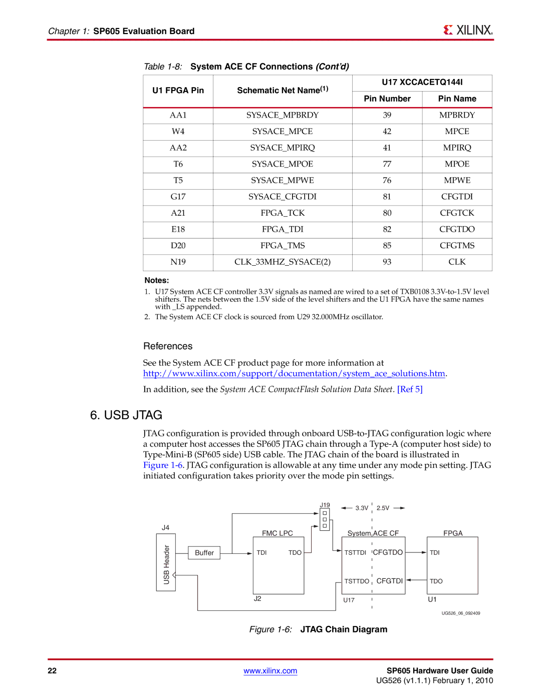
6. USB JTAG
JTAG configuration is provided through onboard
J4
USB Header
| FMC LPC | |
Buffer | TDI | TDO |
J2
J19 | 3.3V | 2.5V |
|
System ACE CF | FPGA |
![]() TSTTDI CFGTDO
TSTTDI CFGTDO ![]() TDI
TDI
TSTTDO CFGTDI ![]() TDO
TDO
U17 | U1 |
UG526_06_092409
Figure 1-6: JTAG Chain Diagram
22 | www.xilinx.com | SP605 Hardware User Guide |
|
| UG526 (v1.1.1) February 1, 2010 |