Xilinx SP605 User Pushbutton Switches, 16 User Pushbutton Switch Typical, Switch Pin, U1 FPGA Pin

Models: SP605

1 67
Download 67 pages 13.67 Kb
Page 42
Image 42
User Pushbutton Switches

Chapter 1: SP605 Evaluation Board

User Pushbutton Switches

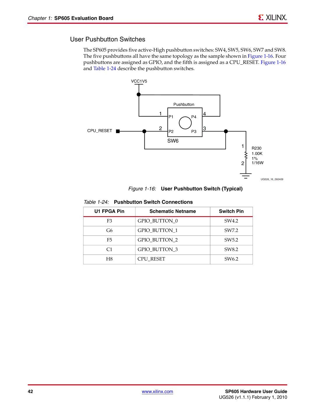
The SP605 provides five active-High pushbutton switches: SW4, SW5, SW6, SW7 and SW8. The five pushbuttons all have the same topology as the sample shown in Figure 1-16. Four pushbuttons are assigned as GPIO, and the fifth is assigned as a CPU_RESET. Figure 1-16and Table 1-24describe the pushbutton switches.

VCC1V5

CPU_RESET

1

2

Pushbutton

P1 P4

P2 P3

4

3

SW6

1R230

1.00K

1%

21/16W

UG526_16_092409

Figure 1-16:User Pushbutton Switch (Typical)

Table 1-24:Pushbutton Switch Connections

U1 FPGA Pin

Schematic Netname

Switch Pin


F3

GPIO_BUTTON_0

SW4.2


G6

GPIO_BUTTON_1

SW7.2


F5

GPIO_BUTTON_2

SW5.2


C1

GPIO_BUTTON_3

SW8.2


H8

CPU_RESET

SW6.2


42

www.xilinx.com

SP605 Hardware User Guide


UG526 (v1.1.1) February 1, 2010

Page 42
Image 42
Xilinx SP605 User Pushbutton Switches, 16 User Pushbutton Switch Typical, 24 Pushbutton Switch Connections, Switch Pin