Release
Visitor and Community Network Access Concentrator
3Com Corporation 5400 Bayfront Plaza Santa Clara, California
Contents
Troubleshooting
127
130 Inability to Connect Broken Session 131
Online Technical Services 141 World Wide Web Site
3Com FTP Site 142
143
Page
Conventions
List conventions that are used throughout this guide
Icon Description
Documentation
Related
Year
Compliance
Features
Major Features Benefits
Visitor
Community
Overview
Applications
MTU/MDU Application
VCN AC Features
VCN AP
VCN AC Front Panel
Local Management
Features Real Time LED Indications
VCN AC Front Panel LEDs
State Used to
Remote Management
Central Management
Overview
Safety Precautions
Installing the VCN Access Concentrator
Précautions de
Sécurité
Sicherheitsvorkeh- rungen
Visitor and Community Network system is installed
For the VCN Access
Preparing the Site
Concentrator
Installing the VCN Access Concentrator
Punch-down Block with a Patch Panel
Installing the VCN Access Concentrator
Punch-Down Block Without a Patch Panel
VCN Access Point Rear Panel
Repeat through for up to 24 telephone lines
Installing the VCN Access Concentrator
VCN Access Concentrator Accessory Set
Access Concentrator 19-inch rack. in the 19-inch Rack
Cable Kit
Part Quantity
Fitting a Bracket for Rack Mounting
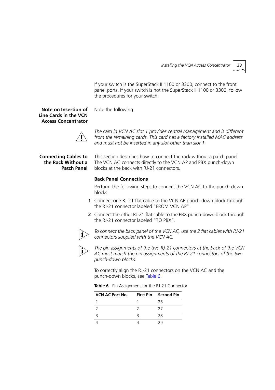
Back Panel Connections
Front Panel Connections
Displays the rack after it has been wire connected
Is P
Patch Panel blocks at the back with RJ-21 connectors
Line Cards in the VCN Access Concentrator
Pin Assignment for the RJ-21 Connector
VCN AC Port No First Pin Second Pin
Female RJ-21 Connector
VCN Access Concentrator Unit Installed Without a Patch Panel
Sequence of Configuration
Inserting MAC Addresses for VCN Access Concentrator Ports
General guidance is provided for non-SuperStack switches
Installing the VCN Access Concentrator
Port No. MAC Address
VCN AC Port and VCN AP MAC Addresses
Installing the VCN Access Concentrator
Automated Procedures for SuperStack II 1100/3300
ConfApp Screen
ConfApp screen appears Figure
Entering the Switch Address
Community Parameter
Removing Wrong Address
Powering Up
Ethernet Switch
VCN Access
SPE-3, SPT-3, G, W
Troubleshooting
Installing the VCN Access Concentrator
Indications
Real Time LED
This chapter describes the following
Status of each line in the VCN AC
Using
Management
Terminal for Local Central Management
Terminal Emulator
Connecting the PC To connect the PC to the LMA port
Type your Login ID and press Enter
Login
Type your password and press Enter
Line CardThis section describes local management
Line Card Menu Hierarchy and Summary
Line Card Main Menu
Line Card Menu Structure
Number Sequence Corresponding to Submenus
Line Card Main Menu of Port
Press Enter to return to the Line Card Main Menu
LC Version
Ethernet Menu
Management Menu
Ethernet Menu options are described in Table
Ethernet Menu Options Feature How to use
Ethernet Traffic Counters
Ethernet Menu Options
Typical Ethernet Traffic Counters Screen
Ethernet Status
Change Ethernet Work Mode Menu
Reset Ethernet Counters
When you discard the operation, the message appears
Setting Internal Loopback Mode
Setting Normal Mode
Hdlc Menu
Hdlc Menu Options Feature How to use
Hdlc Menu options are described in Table
Hdlc Traffic counters
Hdlc Status
Change Hdlc Work Mode
Reset Hdlc Counters
Normal mode is lack of loopbacks
To check the Vdsl parameters
Vdsl Control Menu
Reset All Counters
SNR, signal to noise ratio
Login message appears
Reset the Line Card
Set Vlan ID for Management
LC Configuration Menu
Change Password
Set Ethernet Half/Full Duplex Mode
Respond by entering your new password. The message appears
After any number the user enters, the message appears
Set to Factory Defaults
Through the LMA
To download new software perform the following steps
Procomm Plus window shown in , select Data Send File Figure
Type S the downloading message in appears
Procomm Plus Terminal Screen
Procom Plus Data Send File Menu
Sending File Using Ascii Screen
Status Screen
File Downloaded Messages
Software Execution Messages
Line Card Management
This section describes central management
LMA Access for Central Management
Central Management Menus in the LMA Interface
Login Process
Central Management Menu Hierarchy and Summary
Login Process
Central Management Menu Structure
Central Management Menus and Corresponding Number Sequence
VCN Access Concentrator Menu
To access central management
Management Agent Menu
Line Card Main Menu for Line Card
Slot 1 Line Card Main Menu
Version Information
Hardware and Software Version
Monitoring Menu
Monitoring Menu
Brief Status of All Ports
Refresh Brief Status or View Port Statistical Detail
Detailed Port Status
Select Traffic Counters and Port
Traffic Counters for Selected Port
Vdsl Information for Selected Port
Dialog in appears
Vdsl Information for Selected Port
Reset Port
Control Menu
Change Port Selection in Control Menu
If you type y, the following message appears
If you type N, the message appears
Messages in appear
This is followed by the messages in and , Login prompt
Vdsl Restart
To abort type n and press Enter
Type n and press Enter to abort
Concentrator Configuration Menu
Change Vlan ID for Management
Type 2 and press Enter the following dialog appears
Change Ethernet Half or Full Duplex Mode
Change the Concentrator Password
Type your new password and press Enter. The message appears
Agent Configuration Menu
IP Menu
IP Menu
Discard changes, type n and press Enter n
Save changes, type y and press Enter Messages appear
Close Telnet Session
If a Telnet session exists, the message appears
Set Factory Defaults
Default is n
To reject, type n and press Enter the message appears
Reset Agent
To proceed, type y and press Enter the message appears
Overview
Structure of Remote Menus
Telnet Connection
Telnet Menu Structure
Central Management Menus and Corresponding Number Sequence
VCN Access Concentrator
Telnet Login
Hardware and Software Version
Menu appears
To configure VCN AC management, type 5 in the VCN Access
Exiting the Telnet Management Session
To terminate, type y and press Enter the message appears
Telnet session is closed
Download
Downloading Software to the LCs in the VCN AC
Procedure
VCN Service Switch 10 Front Pane
VCN AP Main Menu
Enter the AC Vlan ID and press Enter. The message appears
VCN AP Software Download Menu
LC Downloading State Table
LC Downloading Results
Enter the AP Vlan ID and press Enter. The message appears
Downloading Software to VCN APs
AP Downloading State Table
Check Software Download for the LC Cards
Download Failed for One or More Line Cards but not All
Download Failed for all LCs and all VCN APs
Check the following Software version of the failed LCs
Check the physical path between the downloading VCN AP
Download Failed for One or More VCN APs but not All
Managing the VCN Access Concentrator
State
Line Power
Problems
Using Front Panel
Indicator LEDs
LEDs to Solve
Ethernet Traffic Counters
Hdlc Traffic Count Indicators
Error message Significance User Action
From Traffic Counts Frame counts
Fatal
Telnet Connection Problems
Telnet Connection Problems
Troubleshooting
Product Specification
Product Specification
Procomm Plus Terminal screen in appears
Terminal Emulation Settings
Number From Left Function Settings
Procomm Plus Settings
137
Setup window opens
Select System Tab
Parity None
Flow control
139
Terminal Emulation Settings
Online Technical
Services
Username anonymous
Access by Analog Modem
Hours a day, 7 days a week
Country Data Rate Telephone Number
Access by Digital Modem
847 262
408 727
Country Telephone Number Asia, Pacific Rim
Europe, South Africa, and Middle East
Country Telephone Number Fax Number
Page
Glossary
Mbaud
Mbps
MiniDIN
Glossary
Glossary
Numbers
Index
Remote software download Requirements
Vlan ID
Index
3Com Corporation Limited Warranty
Governing LAW
EMC Statements