Weighing Indicator
This manual and Marks
Contents
Setting the Parameters of Setpoint Comparison
Compliance with FCC Rules
Compliance
Compliance with European Directives
Introduction
Installation and Precautions
Installation and Precautions
Load Cell Connections
Verifying Load Cell Output and Input Sensitivity
Adjustment of the Load Cell Output
Installing an Option Board
Front Panel Description
Description of Panels and symbols
Rear Panel Description
Other Displays and Symbols
Options
Accessories and options
Standard accessories
Supplemental accessories for printer
Calibration
Items of Calibration Mode
Configuring a Weighing Instrument
Calibration Procedure
Specifying the Range and Unit
Specifying the Resolution, Decimal Point Position and Format
Specifying the Second Range Capacity
Specifying the Second Range Resolution
To Get Stabilized Data
Specifying the Weighing Range of the First Range
Span Calibration
Zero Calibration
Exiting the Calibration Mode
Weighing Range Function
Digital Linearization Function
Setting the Division and Range
Gravity Compensation Function
Gravity Acceleration Table
Calibration Error Code List
Functions
Changing the Function Settings
OFF
Functions
ZERO+TARE = CAL
EXT2
EXT1
EXT3
Comparator
Data Output
Current Loop Output
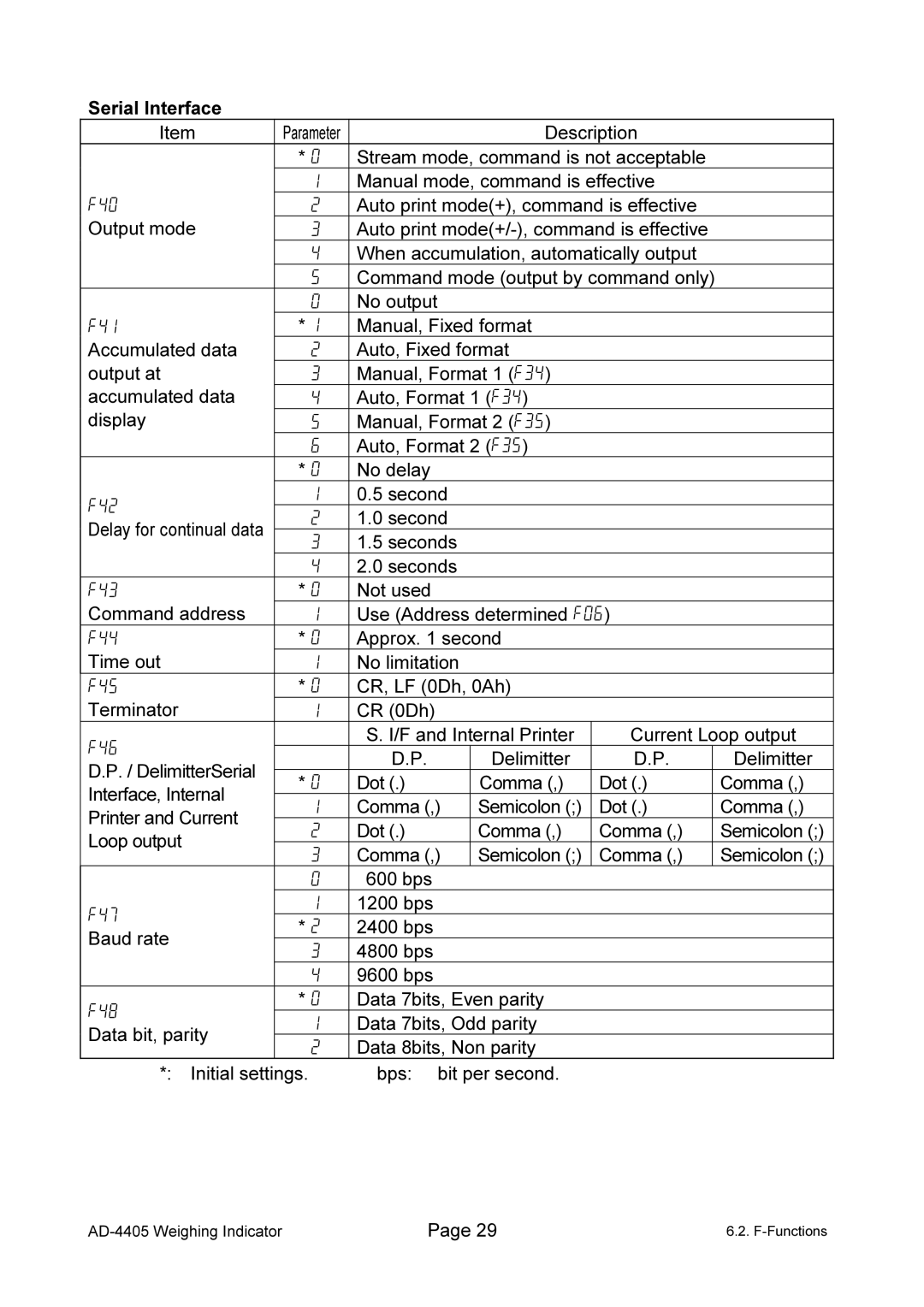
Serial Interface
DD/MM/YY
YY/MM/DD MM/DD/YY
Print Format
CF-Functions
Clearing Tare
Digital Input Preset Tare
Tare
Weighing Tare
Accumulation
Preparation and Specifications
Display and Operation
Parameter
Code Memory
Using Code Memory
Comparison
Weight Check Mode
HI, OK
Condition formula for Comparison
LO, OK
Setting Order and Display for Weight Check Mode
Setting the Upper/Lower Limit Values
Mode
Output and Condition
Setpoint Comparison
Description of Input parameters and Outputs
F22 = 7 Check weighing
Weighing Completion
F22 = 9 Check weighing 3Loss in weight
Simple Batch
Start
Toward the Zero band
Setting the Parameters of Setpoint Comparison
Returns to Zero band
Relations to the Other Functions
Setting the Hold Functions
Hold Function
Display and the Data Output of Hold and Average
MT, MZ, HC
Key input and command in the hold state
Conditions of the Average and Release
TARE, ZERO, SETPOINT, Total
Unit Weight Registration
Using the Counting Function
Counting Function
Key to register the unit weight and return to the piece
13.1 Time and Date Functions
Calendar / Clock
YY/MM/DD
Setting Time and Date
Corrected date is as follows 05 05
Internal Printer OP-06
Replacing the Ink Ribbon
Installing the Printer Paper Special roll paper
Common Printer and Data Output Items
15.1 Data Output / Print Mode
Interval Data Output / Print
Data Number
Interval Data Output / Print output
Setting the Interval Time
Bit Format
16.1 Specifications
RS-232C Interface
Circuit and Pin Connection
Figures
Data Format
Explanation of Commands
Command Format
Commands to Request Data
Commands to Control the Indicator
Changing the Code Memory
Changing the Weight Unit
Set the Limit/Setpoint Value
Commands to Set Parameters
Set the Preset Tare
Set the Unit Weight for Counting Mode
Release the Hold Data
Commands for the Hold Function
Commands to Set the Data Output/ Print Format UFC
Start Averaging to Hold
UFC Command Parameters
UFC Commands
PF2,$DT$TM$LF$AN$SP$TL$LF
$DL
SF1,$ID$DN$CR$LF$GR$UT$CR$LF
’$AN$TL$LF$LF
Circuit
RS-422/RS-485, Relay OutputOP-03
TRM
COM
Switching Between RS-422/RS-485
DC50V
Relay Output & Control Input OP-05
Circuits
Settings
Specifications
19 -20mA Analog Output OP-07
CL1
Current Loop Output OP-08
CL2
Data Format
Current Loop Output
Interface
Specifications
Analog Input and A/D Conversion
Digital Section
General
Dimensions
Memo
Memo
Memo
