ADAM 4000 specifications
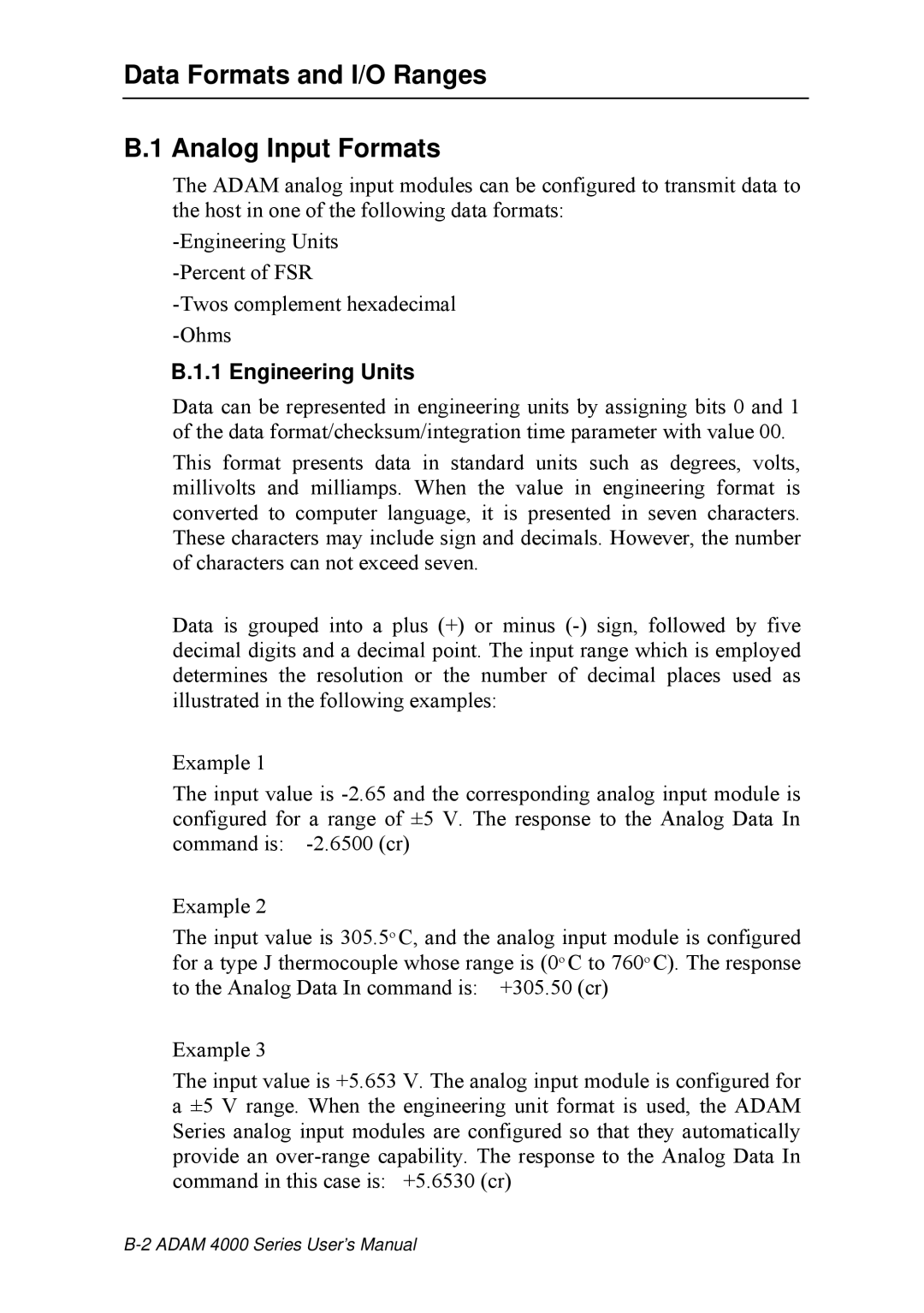
Advantech's ADAM 4000 series is a line of versatile distributed I/O devices designed to bridge the gap between field devices and control systems. Known for its robust design and flexible configurations, the ADAM 4000 series is ideally suited for various industrial applications, including process monitoring, automation control, and data acquisition.One of the notable features of the ADAM 4000 series is its modular architecture. This flexibility allows users to customize their setup by selecting specific I/O modules tailored to their application needs. The series supports a wide range of input and output types, including analog, digital, and relay outputs, making it a comprehensive solution for monitoring and controlling various parameters in a system.
In terms of communication, the ADAM 4000 series boasts multiple connection options, including RS-232, RS-485, and Ethernet. These communication protocols ensure seamless integration with existing control systems and enhance the ability to deploy in various network configurations. Furthermore, the series supports several industrial protocols such as Modbus, enabling easy integration with SCADA systems or PLCs.
One of the standout technologies in the ADAM 4000 series is the use of advanced data acquisition methods. This allows users to capture precise data from sensors and other field devices, which can then be processed and analyzed to improve operational efficiency. The built-in diagnostics features help in quick troubleshooting, minimizing downtime and maintenance costs.
The ADAM 4000 devices are designed for rugged environments, featuring a wide operating temperature range and a high level of resistance to electromagnetic interference. This durability makes them suitable for various industrial conditions, from factory floors to remote monitoring stations.
Additionally, the ADAM.NET SDK provided by Advantech simplifies the development process for software applications. This toolkit allows engineers to build custom applications that effectively interact with the devices, thus enhancing the overall functionality and user experience.
In summary, the Advantech ADAM 4000 series stands out as a reliable and flexible solution for industrial automation needs. Its modular design, diverse communication protocols, advanced data acquisition capabilities, and rugged build quality make it an ideal choice for organizations looking to enhance their monitoring and control systems. Whether in manufacturing, energy management, or environmental monitoring, the ADAM 4000 series offers a robust foundation for any industrial application.
