Reference Guide
Front Panel Display and Softkeys
Reference Guide
Agilent 81130A 400/660 MHz Pulse/Data Generator
Copyright
Warranty
Services and Support
Limitation of Warranty
Exclusive Remedies
Certification
Before Applying Power
Safety Summary
General
Environmental Conditions
Fuses
Ground the Instrument
Do Not Operate in an Explosive Atmosphere
Do Not Remove the Instrument Cover
Protective earth ground terminal Manuals
Safety Symbols
About this Book
Conventions Used in this Book
Contents
102
Agilent 81130A Specifications
103
105
General Programming Aspects
General Programming Aspects
GP-IB Interface Bus
Agilent 81130A Remote Control
DISPlay OFF
Programming Recommendations
OPC?
Common Command Summary
Questionable Status
Status Model
Condition Register
Transition Filters
Event Register
NTR PTR
Enable Register
Standard Event Status Group
Status Byte
OPERation Status Group
QUEStionable Status Group
Programming Reference
Programming Reference
Agilent 81130A Scpi Command Summary
DIGital
Copy
High
Hold
SOURce ROSCillator
STATus OPERation EVENt?
KEY
Parameter RST, Default Values
Default Values, Standard Settings
Load
TTL
TRIGger COUNt PULSes LEVel TERMination SOURce
Programming the Instrument Trigger Modes
Started
Continuous
Gated
Pulses
Pattern
Burst
Started
Manually Starting and Gating
Scpi Instrument Command List
Armmode
Armlevterm
Armsour
Armsens
Output 2 can be used in parallel
Instrument with two Output channels installed
To setup an infinite loop over segment 2 to segment
Use this command to set up a counted loop across one or more
See previous example
Use this command to set up the destination segment
Digpattloopleng
Digpatt
Digpattprbs
Data
–1 Prbs on Output
Segment
Segment 2 to Segment 4 set to all bits set to zero
See
DIGPATTSEGM1DATA2 #1501011
32, 0, 0, 0 segment 1 = 32, segments 2, 3, and 4 =
Restrictions
Be overwritten no undo
DIGPATTSEGM1234TYPE12
Update the hardware with the new pattern data by sending a
DIGitalSTIMulusPATTernUPDate
Pattern generating hardware following a
DIGSIGN12FORM
Disp
Filetype is always blank. a directory name has filesize =
Query
Event
Directoryname
Filename,A,copyname,A
Only select a directory name within the current directory
Directory of the current directory
Mmemdel
Mmemstorstat
Mmeminit
OFF
OUTP12COMP
Output signals are the same at the device-under-test
CORR12EDELay
–25.0 ns to +25.0 ns
CURR12
CURR12OFFSet
Execute the SOURceHOLD CURRent command to enable
∝A 50 Ω into 50 Ω
Amplitude
Execute Sourcehold CURRent command to enable
+10 mA 50 Ω into 50 Ω
Low-level
8V Outputs 50 Ω into short max mA typical
–10 mA 50 Ω into 50 Ω
0V Outputs 50 Ω into short max mA typical
High-level
CURR12LIMSTAT
–10.0 mA
Hz with engineering prefixes, or MHZ for Megahertz
Output limits cannot program the output-levels beyond
00 MHz
Agilent 81131A 1 kHz to 400 MHz
Use this command to enable either of the SOURceVOLTage or
Connector as the frequency source Trigsour EXT
Freqauto
Once
Programming the pulse phase also executes SOURcePULSeHOLD
To 360 constrained by delay and period limits
PHAS12
PULSDCYC12
To 3.00 µs
Specified limits 0.1 – 99.9%, depends on Width & Period
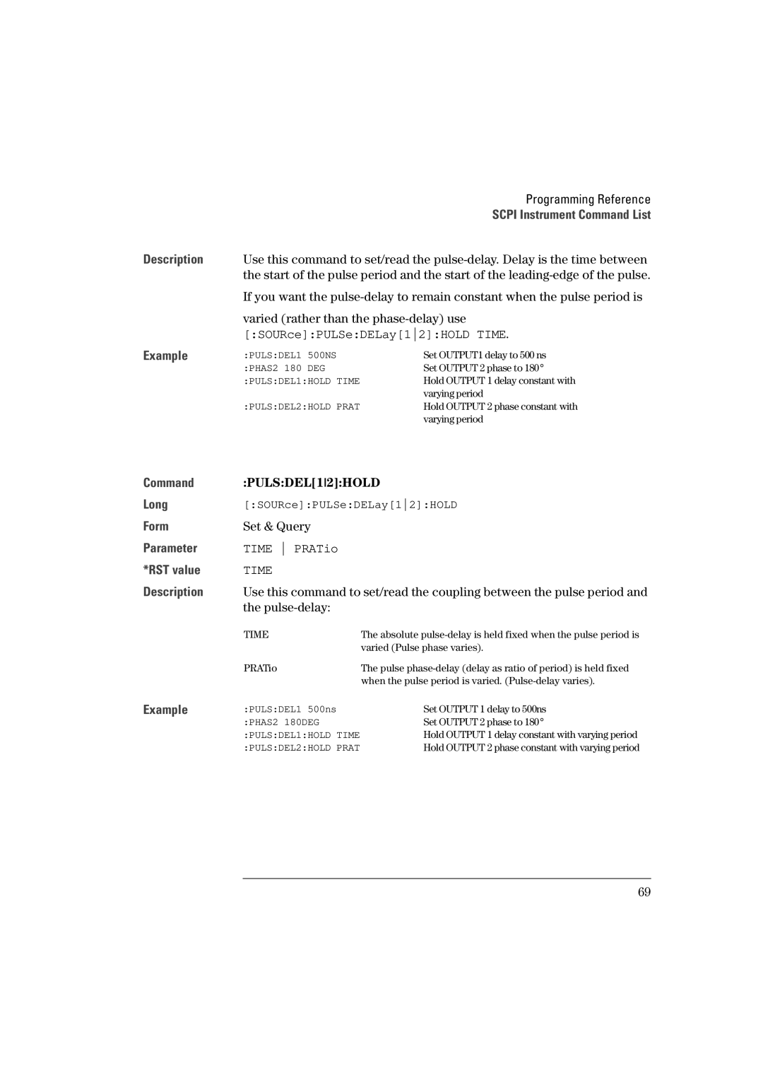
PHAS2 180DEG
Pulse-delay
PULSDEL12UNIT
PULSHOLD12
Pulsper
Available resolution depend on the selected source
Programmed by this command. Note that the specified limits
Connector as the frequency source Trigsour EXT2
Agilent 81131A 2.5 ns to 1 ms Agilent 81132A 1.5 ns to 1 ms
PULSTRAN12
PULSTRAN12UNIT
Agilent 81131A 0.8 ns or 1.6 ns
Trailing-edge = Leading-edge fixed coupled
Within the defined pulse-width
PULSTRIG1MODE
PULSTRIG1POS
PULSTRIG1VOLT
To set width as dutycycle use SOURcePULSeDCYCle12
Roscextfreq
MHz, 2 MHz, 5 MHz or 10 MHz reference signal using
Agilent 81131A 0.10 Vpp to 3.80 Vpp
VOLT12
Agilent 81132A 0.10 Vpp to 2.50 Vpp
Execute
VOLT12HIGH
Execute the SOURceHOLD VOLTage command to enable
VOLT12LOW
+500 mV
Hardware, this is a software limit
–500 mV
Limits are always enabled/disabled together
Scpi Instrument Command List STATusPRESet Long
STATusQUEStionableEVENt?
STATusQUEStionableENABle
STATusQUEStionableCONDition?
STATusQUEStionableNTRansition
Replaced with -350meaning Queue overflow
Message are put into the instruments output buffer
Output example
Systkey
Key Description
Scpi Instrument Command List Specified limits
Systkey 19 sets the instrument to Local mode
Emptied by *RST and returns the value -1 when empty
Systsec
Systpres
SYSTVERS?
Separator between the messages
Active
Trigcoun
Burst
Set by TRIGgerCOUNt. Changes of the number of pulses on
Changes on the channels
TRIGCOUNPULS1? ⇒ TRIGCOUN? ⇒
Triglevterm
Output 1 or Output
Command Trigsour
Scpi Instrument Command List
81132A
Temperature
Used by the instrument
Warranted Performance
Declaration of Conformity
Specifications
Safety
Agilent 81130A Specifications
Power requirements
Maximum Dimensions H x W x D
Weight
Recalibration period
Acoustic Noise Emission
Period & Frequency
Delay
Width
100
Deskew
Compensation for different cable delays
Transition Times
Digital Channel Add
Main Output Level Specifications
External Clock/PLL Reference Input
External Input
104
Specifications of EXT INPUT/CLK-IN REF Input
Externally Started
Externally Gated
Generate continuous pulses, bursts, or patterns
Output Modes
Specification of Trigger Output
Burst Mode
Patterns and Sequences
107
Overprogramming
Human Interface
Non-Volatile Memory
Help Key
Memory Card
Function Code
Programming Times
All checks and display off
110
Pulse Parameter Definitions
Time Reference Point
Trigger Delay
Pulse Period
Pulse Width
Interchannel Delay Skew
Pulse Delay
Transition Time
Linearity
114
Stability
Jitter
Pulse Levels
115
Preshoot, Overshoot, Ringing
Settling Time
116
Repeatability
118
119
Index
120
Scpi
121
122
Front Panel Controls