NI-3101-SIG
AMX Limited Warranty and Disclaimer
Introduction
NetLinx Security within the Web Server
NetLinx Security with a Terminal Connection 117
Troubleshooting 167
NetLinx Integrated Master Controller Features
NI-3101-SIG FG2105-08
NI-3101-SIG Specifications
NI-3101-SIG Specifications
Blue LED bar lights when powered up
MB Flash
RS-232/422/485 Ports 1
D notation is used to represent a device number
IR ports support data mode at limited baud rates and wiring
Distances
NI-3101-SIG Specifications
Page
DevicePortSystem DPS
Where
Structure DEV
Numberportsystem
Installation into an Equipment Rack
Program Run Disable PRD mode
Working with the Configuration DIP switch
PRD Mode Settings
PRD Mode
Configuration Port Connections and Wiring
Mode Description Blue White
Modes and Front Panel LED Blink Patterns
Modes and LED Blink Patterns
Off No power, or the controller is not functioning properly
Port Assignments and Functionality
AXlink Port and LED
Rear Port Assignments are as follows
Wiring Guidelines
Wiring length guidelines
Preparing captive wires
Wiring Guidelines NI-3101 @ 900 mA
Wiring a power connection
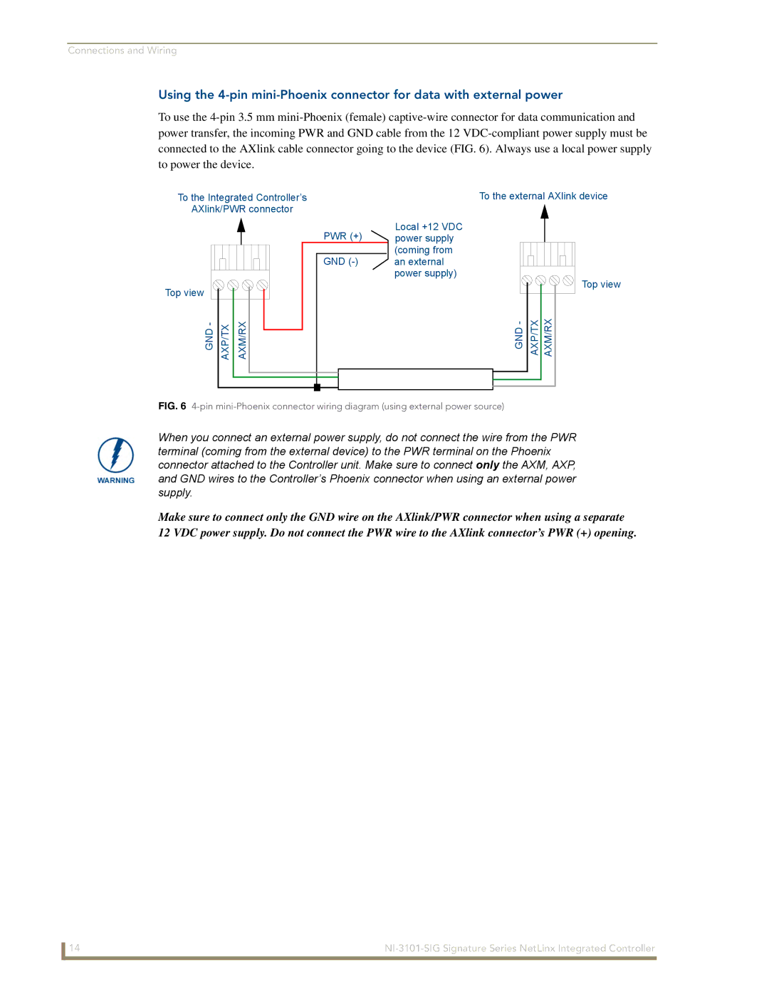
Using the 4-pin mini-Phoenix connector for data and power
GND AXP/TX AXM/RX
DB9 Device Port Connections and Wiring
Relay Port Connections and Wiring
RS-232/422/485 Device Port Wiring Specifications
Pin
Port +12V 6 5 4 3 2
Input/Output I/O Port Connections and Wiring
Relay connections
IR/Serial Port Connections and Wiring
Port Wiring Specifications NI-3101-SIG
IR/Serial Connector Wiring Specifications per Port
Signal Function
Signals Connection Pairing Color
Ethernet/RJ-45 Port Connections and Wiring
Ethernet RJ-45 Pinouts and Signals
Ethernet ports used by the Integrated Controllers
Ethernet Ports Used by the NetLinx Integrated Controllers
Port type Description Standard Port
On-board Master has a built-in FTP server 21/20 TCP
Replacing the Timekeeper Battery
Configuration and Firmware Update
Master Communication Settings dialog box
Communicating with the Master via the Program Port
Setting the System Value
COM1
Using multiple NetLinx Masters
Changing the Device Address of a NetLinx Device
Device Addressing dialog changing the device value
Using the ID Button to Change the Controller’s Device Value
Recommended NetLinx Device numbers
Axcess Devices use Axcess standards
301
Resetting the Factory Default System and Device Values
Obtaining the Master’s IP Address using Dhcp
Network Addresses dialog for a Dhcp IP Address
Configuration and Firmware Update
Assigning a Static IP to the NetLinx Master
Communications Settings dialog box
Communicating with the NI Device via an IP
TCP/IP Settings dialog box
Master Controller User Name and Password dialog box
Verifying the current version of NetLinx Master Firmware
Sample NetLinx Workspace window showing OnLine Tree tab
Upgrading the On-board Master Firmware via an IP
Firmware Kit File usage for NI Controllers
After the last component fails to install, click Done
Select the NI Master’s Kit file from the Files section FIG
Upgrading the NI Controller Firmware via IP
Configuration and Firmware Update
Configuration and Firmware Update
Page
NetLinx Security within the Web Server
Username and profile
Case sensitive
NetLinx Security Terms
NetLinx Security Terms
Accessing an Unsecured Master via an Http Address
Default Security Configuration
Browser Application Frames
Default Security Configuration case-sensitive
Account Group
Master Firmware Security Access Parameters
Telnet Security
Web Control
Managing WebControl Connections
Security Features
Manage WebControl Connection Page Features
Feature Description Compatible Devices Field
Internet
Security Features
Feature Description System Level
Security System Level Security
Group Level
System Level Security
Configuration/Reset, URL list settings, Master
Communication settings, and security parameters
Master must provide a valid username and password
And/or SSH Ports. SSH version 2 is only supported
Setting the system security options for a NetLinx Master
Section on page 49 for more detailed field descriptions
Administrator group account cannot be deleted or modified
Icsp Authentication
You are logged in as a user with Configuration Access
Security Group Level Security
Manage Group
Communication settings, and file transfers
Configure Group Properties
IP configuration/Reset, URL list settings, Master
Adding a new Group
Modifying the properties of an existing Group
Deleting an existing Group
Manage Users
Feature Description Manage Users
Security User Level Security
Configure User Properties
Feature Description Configure User Properties
To this
User Security Details
Configure Users Properties
Feature Description User Security Details
Adding a new User
Sensitive and must be unique
Click the Back button to return to the Manage User
Modifying the properties of an existing User
System Settings
Deleting an existing User
System Settings Manage System
Feature Description Online Tree menu
Manage System Page Components
Online Tree
Feature Description Management menu options
System menu buttons
This button is available from within all Management
Menus
Feature Description Device menu buttons
Port menu buttons
Manage System System Menu Buttons
System Menu Modifying the Date/Time
System Menu Controlling/Emulating Devices on the Master
System Menu Rebooting the Master
System Menu Changing the System Number
Select either the Control or Emulate option
Control/Emulate dialog
Valid Level Data Types and Ranges
Minimum Value Maximum Value
Manage System Diagnostics
Diagnostics dialog showing modify popup
Feature Update Remove Description
Setting up and removing a Diagnostic Filter
Diagnostic Configuration Dialog
System/Device/Port
Feature Description Presets
New Preset. Refer to of this section for more information
NetLinx Security within the Web Server
Setting the Master’s Port Configurations
Default port for each service is listed to the right
Manage System Server
Server Submenu Options
SSH
FTP
Is determined by the user
Modifying the Server Port Settings
Server Port Settings
FeatureDescription
Enabled but the value can not be changed
SSH Port
Address field of the SSH Client application
SSL Server Certificate Creation Procedures
Certificate consists of two different Keys
Server Certificate Entries
Contained in the certificate on the target Master
From an external source
Desired
Server Display SSL Server Certificate Information
Server Creating a self-generated SSL Certificate
Server Regenerating an SSL Server Certificate Request
Server Creating a Request for an SSL Certificate
State/province name must be fully spelled out
Common Steps for Requesting a Certificate from a CA
Communicating with the CA
Server Exporting an SSL Certificate Request
Export SSL Certificate dialog
Server Importing a CA created SSL Certificate
Before importing a CA server certificate
Device Menu Configuring the Network Settings
Manage System Device Menu Buttons
DNS Address
Network Settings Dialog
Feature Description IP Address
Device Menu Developing a URL List
Click the Back button to return to the main URL List dialog
Device Menu Changing the Device Number
URL List dialog with entries
Device Menu Running a Diagnostic Filter
Device Menu Controlling or Emulating a device
Master section on page 67 for more information
Device Menu Viewing the Log
System Settings Manage License
Adding a new license
Removing a license
Manage NetLinx Devices
System Settings Manage NetLinx Devices
Feature Clear List Refresh List Description
Feature Description Device Listings
After a period of time, unable to establish communication
Manage NetLinx Devices Binding/Unbinding Explained
Manage NetLinx Devices Displaying NDP-capable devices
Click the icon to collapse the particular Master’s listing
Manage NetLinx Devices Obtaining NetLinx Device information
MAC Address of the Master in FIG
System Settings Manage Other Devices
Feature Description Dynamic Device Discovery links
Configure Binding Options
Manage Other Devices
Must always be User-Defined devices
Reboot, the selection is cleared
This selection is a one-time occurrence. Upon the next
Deleted via the Purge Bound Modules on Reset selection
What is Dynamic Device Discovery?
Dynamic Device Discovery Concepts
Manage Other Devices Manage Device Bindings
Configuring application-defined devices
What are Application Devices and their association status?
PROGRAMNAME=DDD
Defineconstant Definetype Definevariable
Manage Device Bindings
NetLinx Security within the Web Server
Manage Other Devices Menu Viewing Discovered Devices
View Discovered Devices
Module Properties displayed via a mouse-over popup dialog
Amplifier DocumentCamera SlideProjector AudioConferencer
Switcher
SDK-Class Types
To configure a Static application interface
How do I write a program that uses Dynamic Device Discovery
How do I configure a Run-time installation
Accessing an SSL-Enabled Master via an IP Address
Security Alert and Certificate popups
Certificate Import Wizard
Using your NetLinx Master to control the G4 panel
WebControl VNC installation and Password entry screens
What to do when a Certificate Expires
Connection Details dialog
User has access to the Icsp communication functionality
NetLinx Security Features
NetLinx Security Features
Initial Setup via a Terminal Connection
Accessing the Security configuration options
Setup security Access
Logout Close
NetLinx Security with a Terminal Connection
Or Enter to return to previous menu Security Options
Enabled
Select to change current security option
Command
Items in the Security Options Menu are described below
Option 2 Display system security options for NetLinx Master
Option 3 Add user
Option 4 Edit User
Edit User Menu
Command Description
Password from that point forward
Select to change current access right
Edit User Menu
Access Rights Menu
Option 5 Delete user
Press Enter to display the following Edit Group menu
Option 6 Show the list of authorized users
Option 7 Add Group
Press Enter to return to the Edit Group menu
Path
User1
Results.txt
Or Enter to return to previous menu Set Rights
Select from the following list Administrator Group
Option 8 Edit Group
Option 11 Set Telnet Timeout in seconds
Specify Telnet Timeout in seconds
Option 9 Delete Group
Option 10 Show List of Authorized Groups
Option 13 Make changes permanent by saving to flash
Option 12 Display Telnet Timeout in seconds
Telnet Timeout is 10 seconds
Main Security Menu
Main Security menu is described below
Main Security Menu
Set system security options for
Reset Database
Administrator only function
Group Group administrator Rights All
Security Options FTP Security Enabled
Help menu
Help Menu Options
NAME,COMMAND
SET Icsp TCP Timeout
NAME,STRING SET Date
SET DNS DPS
Logging Into a Session
Help Security
Setup Security
Logout
Page
Master SendCommands
Master SendCommands
Converting Axcess Code to NetLinx Code
Clock
Clockcommands
Sendcommand 010,~IGNOREEXTERNALCLOCKCOMMANDS
G4WC
Used to determine each unique listing
Master IP Local Port SendCommands
Using the ID Button
Master IP Local Port SendCommands
Udpsendto
Configuration Port Commands
PC COM Port Communication Settings
DevicePortSystem DPS
NI-2x00 Port Assignments
Configuration Port Commands
Date
Echo OFF
Echo on
MSG on or MSG OFF
GET Ethernet Mode
Port
OFF DPS, or Name
Chan
On DPS, NAME, Chan
Ping IP Address
Name,Command
Pulse DPS, or Name
PWD
Name,String
Entering N no cancels the operation
Prompts you to enter the new date for the Master
Master-to-Master systems
Rent Java memory heap size as measured in Megabytes. This
Subnet Mask, and Gateway IP Address
Enter Y yes to approve/store the information into the Master
Use caution when adjusting these values
SET Queue Size
Set queue size
Set Queue Size Menu
SET UPD BC Rate
Show Buffers
Each queue Example
Displays a list of any combined devices Example
Displays a list of all devices present on the bus Example
Show LOG
Displays the log of messages stored in the Masters memory
Master logs all internal messages and keeps the most recent
If end is not entered, the last 20 messages will be shown
Show MAX Buffers
Show System
Systems listed are in numerical order Example
Lists all active TCP/IP connections Example
Displays the current time on the Master Example
ESC Pass Codes
WindowsTM client programs
Linux Telnet client
Escape Pass Codes
LED Disable/Enable SendCommands
LED SendCommands
RS232/422/485 Ports Channels
RS232/422/485 ports are Ports
These examples DEV = device
RS-232/422/485 SendCommands
RS-232/422/485 SendCommands
GET Baud
Hsoff
Hson
Rxclr
SET Baud
Tset Baud
Txclr
Xoff
XON
RS-232/422/485 SendString Escape Sequences
RS-232/422/485 SendString Escape Sequences
Command Description 27,20,1
IR / Serial Ports Channels
IR / Serial Ports Channels
Sendstring DEV,27,20,1
IR/Serial SendCommands
IR/Serial SendCommands
Caroff
Caron
GET Mode
Ctof
Cton
Iroff
PON
POD
POF
Ptof
Pton
Meters for the IR Ports
SET IO Link
SET Mode
Sendcommand IR1,SET Mode IR
Sendcommand IR1, SP,25
Short cable length 10 feet
Sendcommand DEV,XCHM extended channel mode
Sendcommand IR1,XCHM
Sendcommand IR1,XCH
Xchm
Input/Output SendCommands
SendCommands
GET Input
SET Input
Troubleshooting Information
TCP/IP
Page
It’s Your World Take Control