Advanced Management
For example, assume a
Using GVRP, switches A and C can register their interest in VLAN #2 with switch B. Then switch B can join the VLAN #2 topology when it receives frames tagged with that VID. Once it does, it can then pass that VLAN traffic to switches A and C.
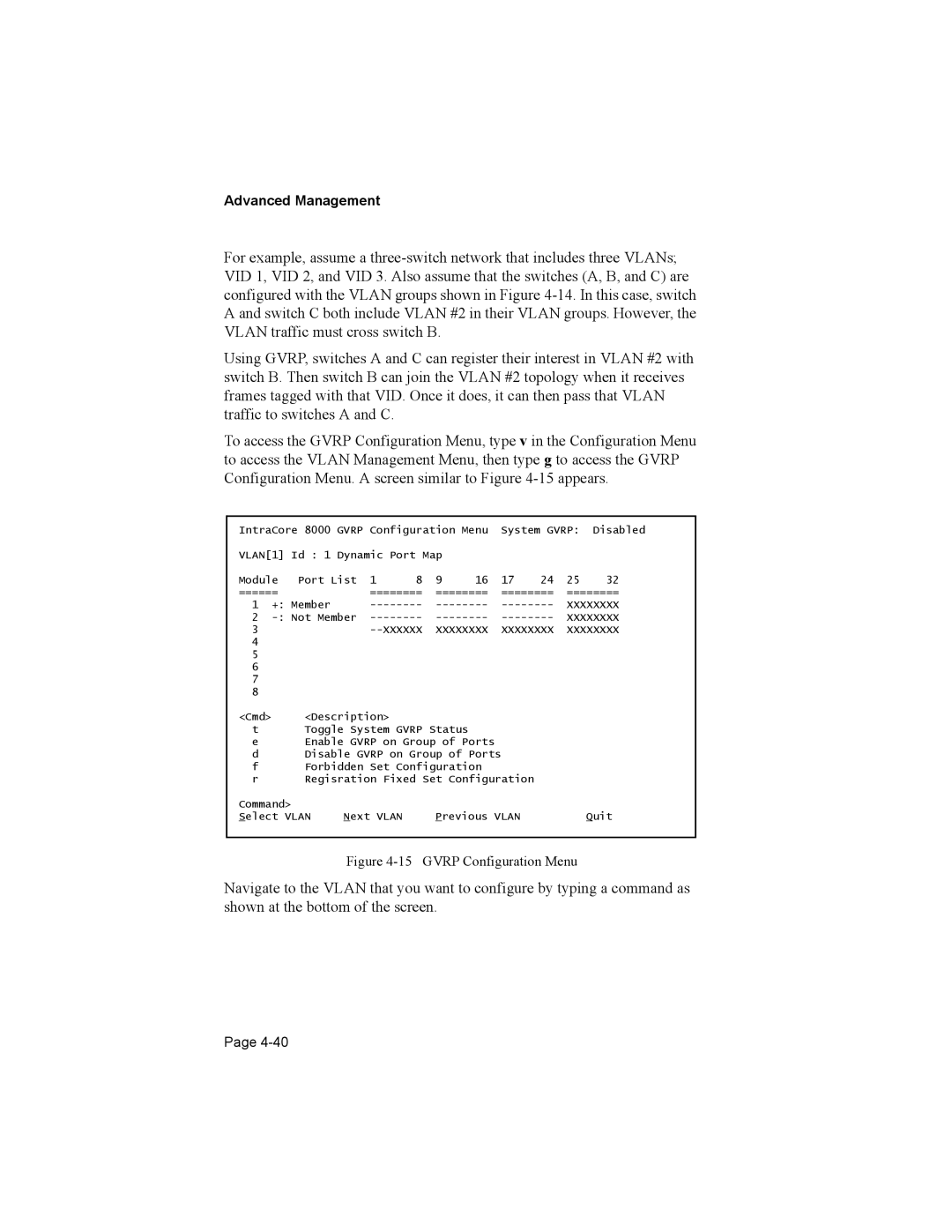
To access the GVRP Configuration Menu, type v in the Configuration Menu to access the VLAN Management Menu, then type g to access the GVRP Configuration Menu. A screen similar to Figure
IntraCore 8000 GVRP Configuration Menu System GVRP: Disabled
VLAN[1] Id : 1 Dynamic Port Map
Module | Port List | 1 | 8 | 9 | 16 | 17 | 24 | 25 | 32 | |
====== |
| ======== | ======== | ======== | ======== | |||||
1 | +: Member | XXXXXXXX | ||||||||
2 | XXXXXXXX | |||||||||
3 |
|
|
| XXXXXXXX | XXXXXXXX | XXXXXXXX | ||||
4 |
|
|
|
|
|
|
|
|
|
|
5 |
|
|
|
|
|
|
|
|
|
|
6 |
|
|
|
|
|
|
|
|
|
|
7 |
|
|
|
|
|
|
|
|
|
|
8 |
|
|
|
|
|
|
|
|
|
|
<Cmd> |
| <Description> |
|
|
|
|
|
|
| |
t |
| Toggle System GVRP Status |
|
|
|
|
| |||
eEnable GVRP on Group of Ports
dDisable GVRP on Group of Ports
fForbidden Set Configuration
r Regisration Fixed Set Configuration
Command> |
|
|
|
Select VLAN | Next VLAN | Previous VLAN | Quit |
Figure 4-15 GVRP Configuration Menu
Navigate to the VLAN that you want to configure by typing a command as shown at the bottom of the screen.
Page