Cables, Connectors, and Ports Table
Table
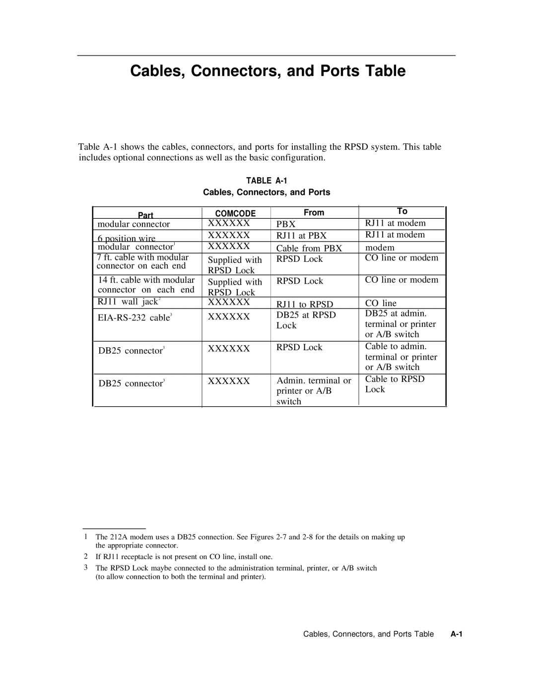
TABLE
Cables, Connectors, and Ports
| Part |
| COMCODE | From | To |
|
|
|
| ||||
| modular connector |
| XXXXXX | PBX | RJ11 at modem |
|
| 6 position wire |
| XXXXXX | RJ11 at PBX | RJ11 at modem |
|
| modular connector1 |
| XXXXXX | Cable from PBX | modem |
|
| 7 ft. cable with modular |
| Supplied with | RPSD Lock | CO line or modem |
|
| connector on each end |
| RPSD Lock |
|
|
|
|
|
|
|
|
| |
| 14 ft. cable with modular |
| Supplied with | RPSD Lock | CO line or modem |
|
| connector on each end |
| RPSD Lock |
|
|
|
| RJ11 wall jack2 |
| XXXXXX | RJ11 to RPSD | CO line |
|
|
| XXXXXX | DB25 at RPSD | DB25 at admin. |
| |
|
|
|
| Lock | terminal or printer |
|
|
|
|
|
| or A/B switch |
|
| DB25 connector3 |
| XXXXXX | RPSD Lock | Cable to admin. |
|
|
|
|
|
| terminal or printer |
|
|
|
|
|
| or A/B switch |
|
|
|
|
|
|
|
|
| DB25 connector3 |
| XXXXXX | Admin. terminal or | Cable to RPSD |
|
|
|
|
| printer or A/B | Lock |
|
|
|
|
| switch |
|
|
1The 212A modem uses a DB25 connection. See Figures
2If RJ11 receptacle is not present on CO line, install one.
3The RPSD Lock maybe connected to the administration terminal, printer, or A/B switch (to allow connection to both the terminal and printer).
Cables, Connectors, and Ports Table |