To connect the RPSD Lock device to the administration terminal or printer, use the following procedure:
1Using Table
2Make up the appropriate connector for the terminal or printer according to the pin descriptions in Table
3Connect the first DB25 connector to the Aux. Port on the back of the RPSD Lock.
4Connect the other end of the cable you just made up to the terminal or printer, as appropriate.
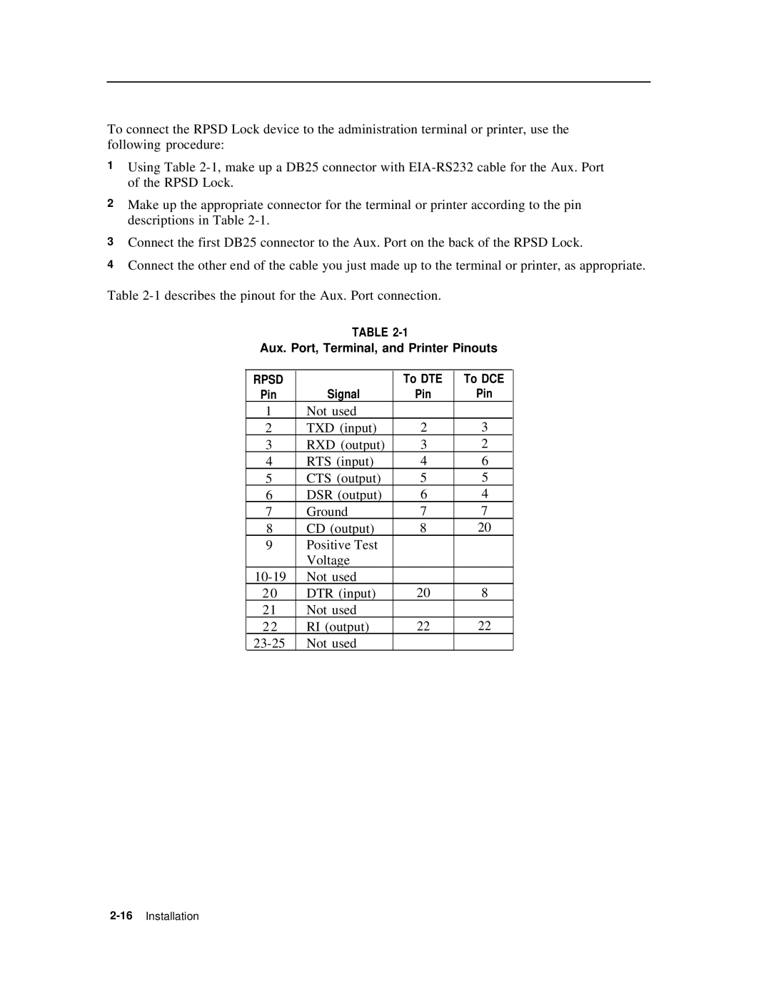
Table
TABLE
Aux. Port, Terminal, and Printer Pinouts
RPSD |
| To DTE | To DCE |
Pin | Signal | Pin | Pin |
1 | Not used |
|
|
2 | TXD (input) | 2 | 3 |
3 | RXD (output) | 3 | 2 |
4 | RTS (input) | 4 | 6 |
5 | CTS (output) | 5 | 5 |
6 | DSR (output) | 6 | 4 |
7 | Ground | 7 | 7 |
8 | CD (output) | 8 | 20 |
9 | Positive Test |
|
|
| Voltage |
|
|
Not used |
|
| |
2 0 | DTR (input) | 20 | 8 |
21 | Not used |
|
|
2 2 | RI (output) | 22 | 22 |
Not used |
|
|