2
3
4
5
6
7
8
20
RPSD (DCE)
2
3
4
5
6
7
8
20
Printer (DCE)
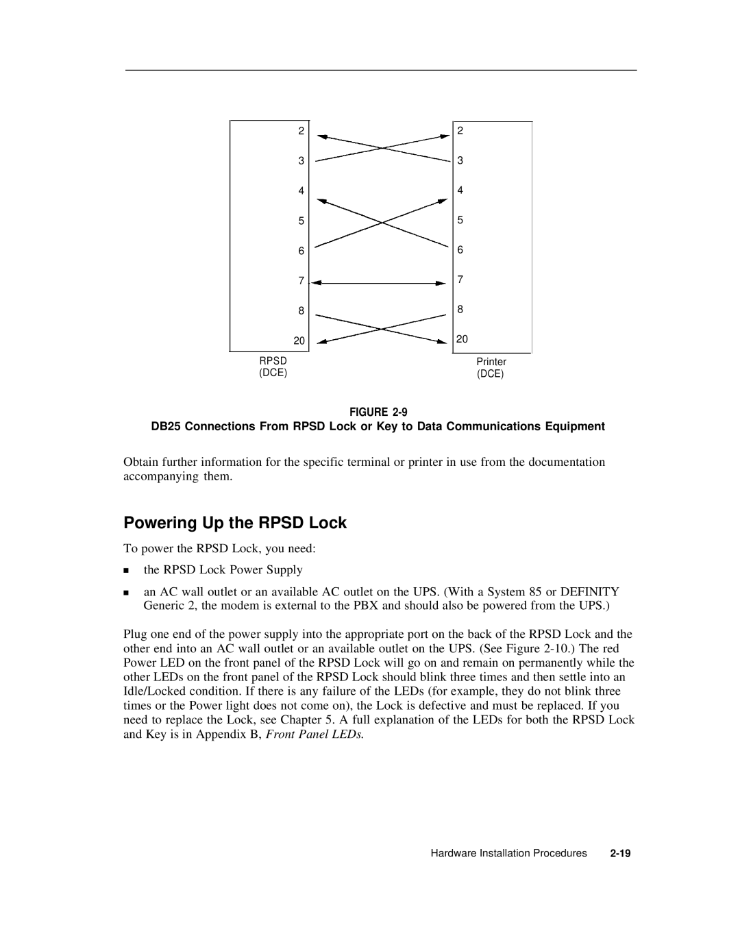
FIGURE
DB25 Connections From RPSD Lock or Key to Data Communications Equipment
Obtain further information for the specific terminal or printer in use from the documentation accompanying them.
Powering Up the RPSD Lock
To power the RPSD Lock, you need:
■the RPSD Lock Power Supply
■an AC wall outlet or an available AC outlet on the UPS. (With a System 85 or DEFINITY Generic 2, the modem is external to the PBX and should also be powered from the UPS.)
Plug one end of the power supply into the appropriate port on the back of the RPSD Lock and the other end into an AC wall outlet or an available outlet on the UPS. (See Figure
Hardware Installation Procedures |