RS232/Keypad Installation Procedure: (optional keypad – LXKP)
Optional Remote Keypad Installation
The keypad may be remotely mounted and sealed to NEMA 4 specification by using the gasket and 6 ft (1.8m) cable included. The keypad assembly is complete with the screws and gasket required to mount it to an enclosure. The gasket has adhesive on one side that must be placed toward the enclosure.
Tools Required:
•Center punch.
•3/16" drill bit (for clearance mounting holes).
•1/2" (12.7) and
•(4)
•Remote keypad mounting template. A tear out copy is provided at the end of this manual for your convenience.
Mounting Instructions: (see remote keypad mounting template)
1.Locate a flat mounting surface. Material should be sufficient thickness (14 gauge minimum).
2.Place the template on the mounting surface or mark the holes as shown.
3.Accurately center punch the 4 mounting holes (labeled E for SAE or M for metric) and the three large
4.Drill four 3/16" holes (at E or M).
5.Make the three large
6.Debur knockout and mounting holes making sure the panel stays clean and flat.
7.Apply the adhesive backed gasket to the enclosure.
8.Assemble the keypad to the panel.
![]() Caution: To prevent keypad damage, be sure keypad mounting screws do not extend more than 0.2 (5) into keypad assembly.
Caution: To prevent keypad damage, be sure keypad mounting screws do not extend more than 0.2 (5) into keypad assembly.
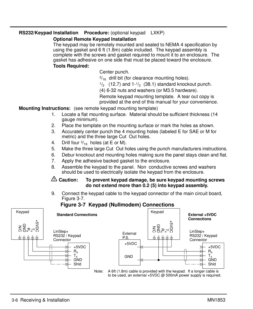
9.Connect the keypad cable to the keypad connector of the main circuit board, Figure
Keypad |
|
|
|
| |||
x GND N/C | x | +5VDC | |||||
|
| T R |
|
| |||
|
|
|
|
|
|
|
|
|
|
|
|
|
|
|
|
|
|
|
|
|
|
|
|
Figure 3-7 Keypad (Nullmodem) Connections
Standard Connections |
| Keypad |
|
| External +5VDC |
|
|
|
| ||
|
|
|
| +5VDC | Connections |
LinStep+ |
| x GND N/C | x | LinStep+ | |
| External | T R |
|
| |
RS232 / Keypad |
|
|
| RS232 / Keypad | |
P.S. |
|
|
| ||
Connector |
|
|
| Connector | |
+5VDC |
|
|
| ||
+5VDC |
|
|
| +5VDC | |
|
|
|
| ||
Rx |
|
|
|
| Rx |
Tx | GND |
|
|
| Tx |
GND |
|
|
|
| GND |
Shld |
|
|
|
| Shld |
Note: A 6ft (1.8m) cable is provided with the keypad. If a longer cable is to be used, an external +5VDC @ 500mA power supply is required.
MN1853 |
