|
| Table |
Char | Keypad Display | Input Character Description |
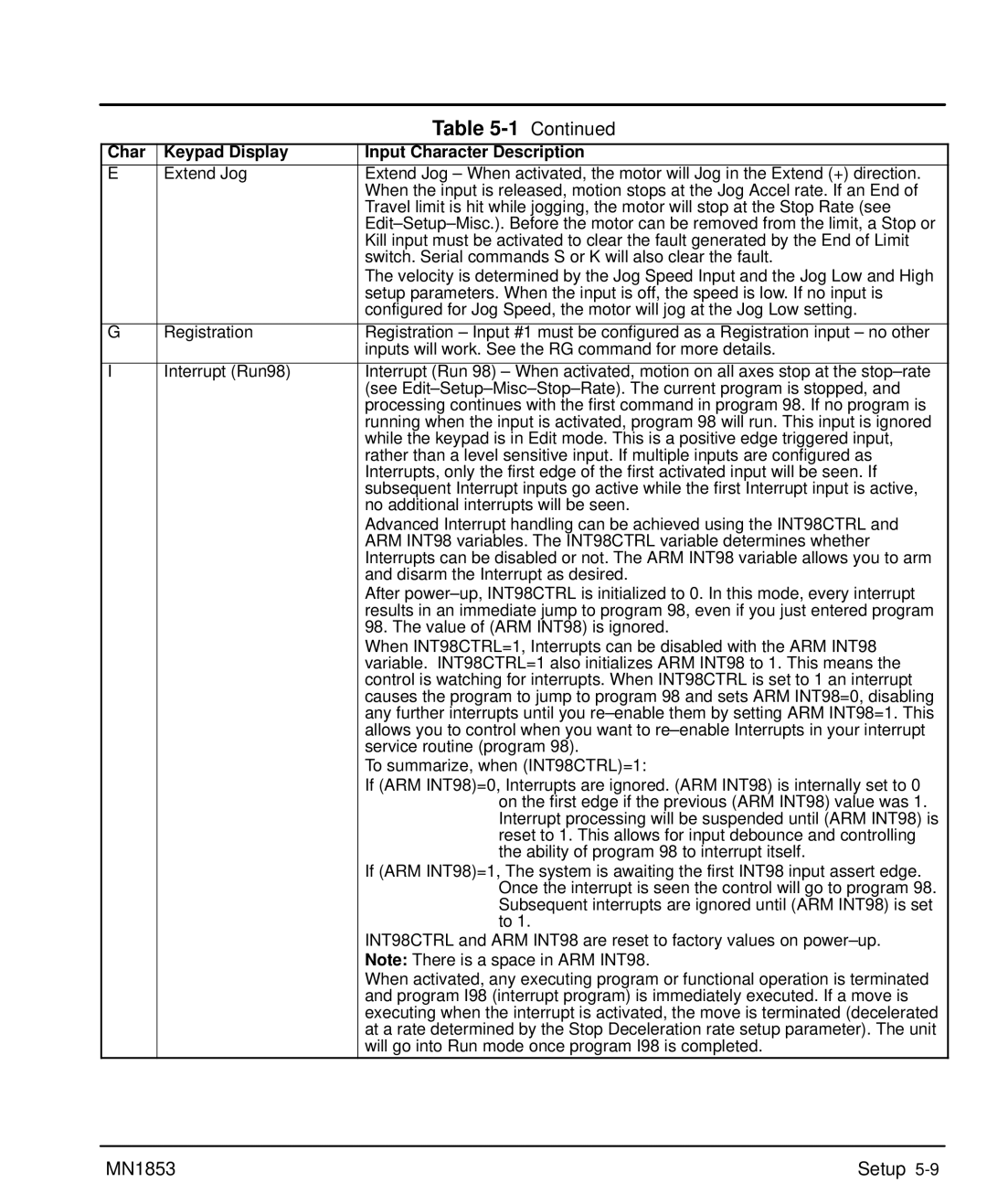
E | Extend Jog | Extend Jog – When activated, the motor will Jog in the Extend (+) direction. |
|
| When the input is released, motion stops at the Jog Accel rate. If an End of |
|
| Travel limit is hit while jogging, the motor will stop at the Stop Rate (see |
|
| |
|
| Kill input must be activated to clear the fault generated by the End of Limit |
|
| switch. Serial commands S or K will also clear the fault. |
|
| The velocity is determined by the Jog Speed Input and the Jog Low and High |
|
| setup parameters. When the input is off, the speed is low. If no input is |
|
| configured for Jog Speed, the motor will jog at the Jog Low setting. |
|
|
|
G | Registration | Registration – Input #1 must be configured as a Registration input – no other |
|
| inputs will work. See the RG command for more details. |
|
|
|
I | Interrupt (Run98) | Interrupt (Run 98) – When activated, motion on all axes stop at the |
|
| (see |
|
| processing continues with the first command in program 98. If no program is |
|
| running when the input is activated, program 98 will run. This input is ignored |
|
| while the keypad is in Edit mode. This is a positive edge triggered input, |
|
| rather than a level sensitive input. If multiple inputs are configured as |
|
| Interrupts, only the first edge of the first activated input will be seen. If |
|
| subsequent Interrupt inputs go active while the first Interrupt input is active, |
|
| no additional interrupts will be seen. |
|
| Advanced Interrupt handling can be achieved using the INT98CTRL and |
|
| ARM INT98 variables. The INT98CTRL variable determines whether |
|
| Interrupts can be disabled or not. The ARM INT98 variable allows you to arm |
|
| and disarm the Interrupt as desired. |
|
| After |
|
| results in an immediate jump to program 98, even if you just entered program |
|
| 98. The value of (ARM INT98) is ignored. |
|
| When INT98CTRL=1, Interrupts can be disabled with the ARM INT98 |
|
| variable. INT98CTRL=1 also initializes ARM INT98 to 1. This means the |
|
| control is watching for interrupts. When INT98CTRL is set to 1 an interrupt |
|
| causes the program to jump to program 98 and sets ARM INT98=0, disabling |
|
| any further interrupts until you |
|
| allows you to control when you want to |
|
| service routine (program 98). |
|
| To summarize, when (INT98CTRL)=1: |
|
| If (ARM INT98)=0, Interrupts are ignored. (ARM INT98) is internally set to 0 |
|
| on the first edge if the previous (ARM INT98) value was 1. |
|
| Interrupt processing will be suspended until (ARM INT98) is |
|
| reset to 1. This allows for input debounce and controlling |
|
| the ability of program 98 to interrupt itself. |
|
| If (ARM INT98)=1, The system is awaiting the first INT98 input assert edge. |
|
| Once the interrupt is seen the control will go to program 98. |
|
| Subsequent interrupts are ignored until (ARM INT98) is set |
|
| to 1. |
|
| INT98CTRL and ARM INT98 are reset to factory values on |
|
| Note: There is a space in ARM INT98. |
|
| When activated, any executing program or functional operation is terminated |
|
| and program I98 (interrupt program) is immediately executed. If a move is |
|
| executing when the interrupt is activated, the move is terminated (decelerated |
|
| at a rate determined by the Stop Deceleration rate setup parameter). The unit |
|
| will go into Run mode once program I98 is completed. |
MN1853 | Setup |
