|
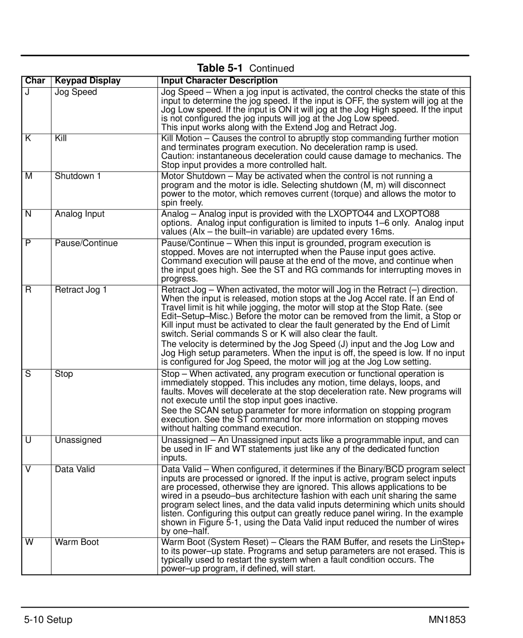
| Table |
Char | Keypad Display | Input Character Description |
J | Jog Speed | Jog Speed – When a jog input is activated, the control checks the state of this |
|
| input to determine the jog speed. If the input is OFF, the system will jog at the |
|
| Jog Low speed. If the input is ON it will jog at the Jog High speed. If the input |
|
| is not configured the jog inputs will jog at the Jog Low speed. |
|
| This input works along with the Extend Jog and Retract Jog. |
K | Kill | Kill Motion – Causes the control to abruptly stop commanding further motion |
|
| and terminates program execution. No deceleration ramp is used. |
|
| Caution: instantaneous deceleration could cause damage to mechanics. The |
|
| Stop input provides a more controlled halt. |
M | Shutdown 1 | Motor Shutdown – May be activated when the control is not running a |
|
| program and the motor is idle. Selecting shutdown (M, m) will disconnect |
|
| power to the motor, which removes current (torque) and allows the motor to |
|
| spin freely. |
N | Analog Input | Analog – Analog input is provided with the LXOPTO44 and LXOPTO88 |
|
| options. Analog input configuration is limited to inputs |
|
| values (AIx – the |
|
|
|
P | Pause/Continue | Pause/Continue – When this input is grounded, program execution is |
|
| stopped. Moves are not interrupted when the Pause input goes active. |
|
| Command execution will pause at the end of the move, and continue when |
|
| the input goes high. See the ST and RG commands for interrupting moves in |
|
| progress. |
R | Retract Jog 1 | Retract Jog – When activated, the motor will Jog in the Retract |
|
| When the input is released, motion stops at the Jog Accel rate. If an End of |
|
| Travel limit is hit while jogging, the motor will stop at the Stop Rate. (see |
|
| |
|
| Kill input must be activated to clear the fault generated by the End of Limit |
|
| switch. Serial commands S or K will also clear the fault. |
|
| The velocity is determined by the Jog Speed (J) input and the Jog Low and |
|
| Jog High setup parameters. When the input is off, the speed is low. If no input |
|
| is configured for Jog Speed, the motor will jog at the Jog Low setting. |
|
|
|
S | Stop | Stop – When activated, any program execution or functional operation is |
|
| immediately stopped. This includes any motion, time delays, loops, and |
|
| faults. Moves will decelerate at the stop deceleration rate. New programs will |
|
| not execute until the stop input goes inactive. |
|
| See the SCAN setup parameter for more information on stopping program |
|
| execution. See the ST command for more information on stopping moves |
|
| without halting command execution. |
|
|
|
U | Unassigned | Unassigned – An Unassigned input acts like a programmable input, and can |
|
| be used in IF and WT statements just like any of the dedicated function |
|
| inputs. |
|
|
|
V | Data Valid | Data Valid – When configured, it determines if the Binary/BCD program select |
|
| inputs are processed or ignored. If the input is active, program select inputs |
|
| are processed, otherwise they are ignored. This allows applications to be |
|
| wired in a |
|
| program select lines, and the data valid inputs determining which units should |
|
| listen. Configuring this output can greatly reduce panel wiring. In the example |
|
| shown in Figure |
|
| by |
W | Warm Boot | Warm Boot (System Reset) – Clears the RAM Buffer, and resets the LinStep+ |
|
| to its |
|
| typically used to restart the system when a fault condition occurs. The |
|
|
| MN1853 |