LinStep+ Single-Axis Microstepping Indexer/Driver
Table of Contents
Prog To PAD From
Prog
POS
Troubleshooting
Iv Table of Contents MN1853
CE Compliance
Limited Warranty
Section General Information
Could result in damage to property
Product Notice Intended use
Could result in injury or death
Do not touch any circuit board, power device or electrical
Connection before you first ensure that power has been
Do not apply AC power before you ensure that grounds are
Voltages that are conducted to its power input terminals.
Extend more than 0.2 5 into keypad assembly
Instead, we recommend using a four wire Wye
Power is removed from the drive
Driver should have specifications compatible to the drive
Motors
Section Product Overview
Overview
Product Overview MN1853
Section Receiving and Installation
Power Dissipation
Mechanical Installation
Receiving & Inspection
Recommended System Grounding 1 phase for CE
Recommended System Grounding for UL
Input Power Conditioning
System Grounding Ungrounded Distribution System
Wire Size and Protection Devices
Delay a
Europe
Baldor
Connection Locations 115VAC, 1 Axis
Keypad Nullmodem Connections
Tools Required
9 & 25 Pin RS-232 Cable Connections for UL Installations
RS-232 PC Connections
Daisy Chain Connections
Rules for Daisy Chain Operation
What is a termination resistor?
Where are these resistors placed?
RS485 PC Connections
How many resistors should my system have?
13 RS485 4 Wire Multi-Drop for UL Installations
ET±
Discrete I/O Connections
Limits Connections
+5VDC
Encoder Signal PVS100 Danaher 9-Pin D
Encoder Color Code
Motor Connector
AY0165A00 Leadwire Connection 9 pin to flying leads
Interlock Intlk
Ground GND
21 Opto Racks
PNP
DB25 Pin to Screw Terminal Converter
PNP Converter
Start-Up Procedure
Power Off Checks
Power On Checks
Action Display Comments
F1, F2, F3
Section Keypad Operation
Overview
Menu Key
Main Menu
JOG F2
Menus
Alpha
Decimal Point
Comma
Edit Menu
New Program
Save the program
Edit an existing program
Naming a program
Example of Naming a Program
Entering Characters with the Alpha Key In edit mode
Use the =O keys for additional alpha characters
Edit, Setup Submenu
Submenu Setup Parameter Description of Setup Parameter
Press EDIT, POS F3 Press YES F1 or no F3
Pressing Help in the Main Menu
Pressing Help in Menus and Sub-Menus
Pressing Help In the Program Edit function
Sequentially Eeprom message disappears
COPY, to PAD Submenu
Keypad Operation MN1853
Section Setup
Procedure Format Definition
AR unloaded + 12.987 x log + log 155 Tm * Jr
Value Range
Value OFF
Fine-Tuning Offsets
Value High
Application Notes
Range N/A
Value
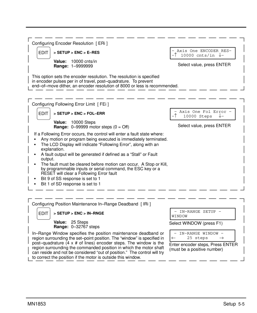
Configuring Encoder Resolution ERi
Configure Your Application Mechanics
Value inch
Configure the I/O
Char Keypad Display Input Character Description
No additional interrupts will be seen
By one-half
AMP Fault
Fault
Brake
Over Current
Configure the Optional Lxopto 44/88
Configure the Output States
Configure End of Travel Switch Polarity
Configure JOG Parameters
Configure Home Parameters
Configuring Home Edge HEi
Configure Power-up Program
Configure Serial Communications
Value Enabled Range Enabled, Disabled
Configure Miscellaneous Setup Parameters
Data Type Description of Display Data Type
POS1
VEL1
General Password Rules
Password Type Description Gives access to these menus
Setup MN1853
Keypad Program Command List
Section Keypad Programming
Value Units
Examples
AC2 DE.5 VE12 DA3 GO DA3 GO DA3 GO
Value Units Range
Example
DC Distance to Change
Example Distance to Change
Examples of DC move profiles, AC = seconds, VE=ips
AC.1 VE60 DI2 GO DI1 GO DI-4 GO
IF2,1 EN EB DI2 GO
Value Units Range N/A
LP2 DI3 GO EB
=12 =13 =17 =18 =22 =23
=26 =27 =28
RUN Edit
Copy DEL
Example 3-Screen Menu Program
GH Start Home
Value N/A Units N/A Range N/A
Value N/A Units N/A Range i=1-16
Units Range N/A
=1-400, name = any legal program name
IF10 Gtpart a EB
Units Range
IFPARTS=25 GS20 EB
Dilength
IV12,LENGTH
Lppieces
Value Units N/A Range N/A
Syntax MC+ MC Move Continuous
Move Continuous
MS27,COUNT
Powerup ONL,GTON EOT
Gthome
Main
VE5 DA20 GO
= starting output number
Syntax RGr RG Registration
SQRESULT=0 SQ27.96,SQRESULT
Value N/A Units N/A
ST1 AC1 DE1 VE25 DA6 GO VE50 DA0 GO EN
Value N/A Units seconds
Syntax VEr VE Velocity
Programming Overview
Summary of Expressions, Operators and Functions
Helpful Hints Programming your application
Example of Hosted Mode
Variables
Program
Variable Names
Built-in Variables
Variable Name Description of Built-in Variable Type
Using Built-in Variable Arowrel
Lpnumber
Non-Volatile Variables
Parts
Boolean Operators
AO15=VOLTAGE + Error
Arithmetic Operands and Equations
Logical Operators
Increment/Decrement Variables
Expressions Other Programming Samples
WTAI12MAX Temp
Setting an Output=On on-the-fly
Create a Message and Read an Input Variable
Read a 4 Digit BCD number, 2 Digits at a time
Reading an Analog Input Value
GET 4 Bcds
Digit BCD=4 Digit BCD+2TW
Additional Information General
Section Troubleshooting
1Operating Mode Indications, 1 Axis
Additional Information
Serial Communications Problems
Troubleshooting MN1853
LinStep+ LX 1 P 1 A- 0xF9
Section Specifications & Product Data
Identification
General Specifications
Protection & Indicators Description
VAC
VDC
Dimensions
Specifications & Product Data MN1853
Wiring of Shielded Screened Cables
Section CE Guidelines
CE Declaration of Conformity
EMC Conformity and CE Marking
EMC Wiring Technique
Grounding Earth
EMC Installation Instructions
Cable Screens Grounding
Encoder Cable Grounding
Input Signal Cable Grounding
Simulated Encoder Output Cable Grounding
Appendix a
Programming Template
Appendix MN1853
MN1853 Appendix A-3
Remote Keypad Mounting Template
Baldor Electric Company
Baldor Electric Company MN1853 01 C&J
LinStep+ Single-Axis Microstepping Indexer/Driver