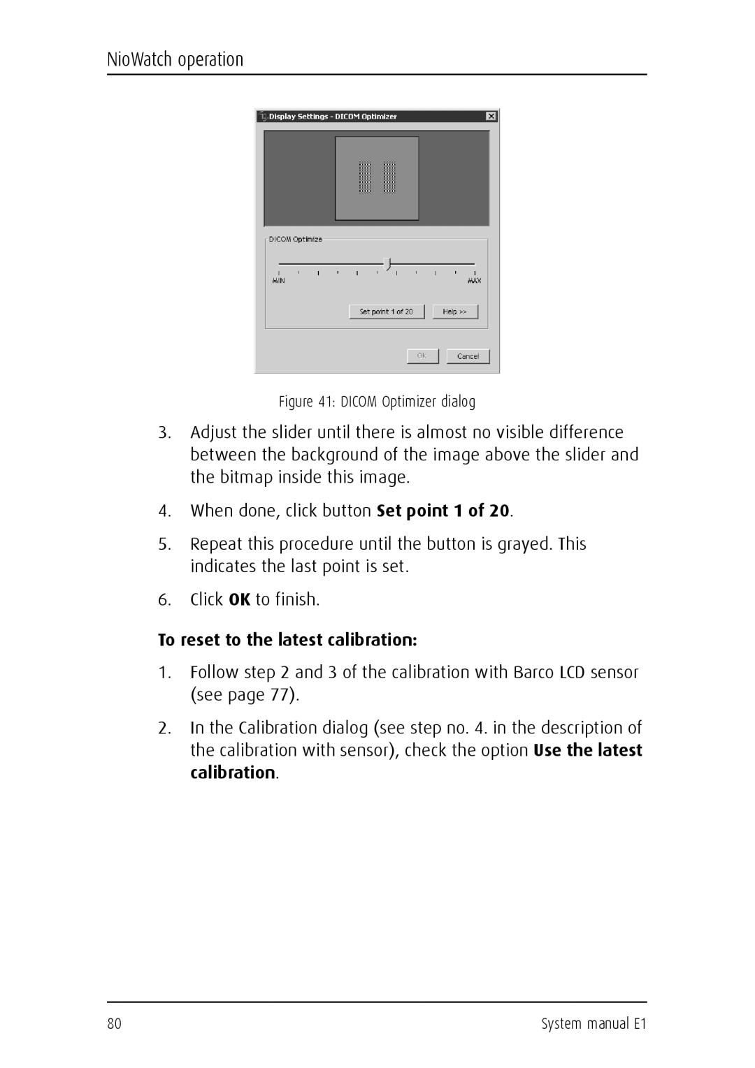
System manual E1
Installation & User Manual
Copyright notice
Copyright notice
This page intentionally left blank
Copyright notice
System manual E1
Table of Contents
Table of Contents
Display controller software installation
Table of Contents
System manual E1
Preface
This page intentionally left blank
Preface
System manual E1
FCC notice
Trademarks
Preface
Disposal Information
Canadian notice
Preface
Power connection
Safety Instructions
Safety Instructions
Degree of safety flammable anesthetic mixture
Safety Instructions
Installation
Water and moisture
Ventilation
CE, IEC 60950, UL 60950, CAN/CSA C22.2 No. 60950 c-UL
This apparatus conforms to
National Scandinavian Deviations for Cl
Safety Instructions
Symbols used throughout the manual
Explanation of symbols
Symbols on the display and power supply
System manual E1
Introduction
This page intentionally left blank
Introduction
System manual E1
Overview
Features of the BarcoMed Nio display controller
Overview
BarcoMed Nio display controller overview
MFGD 1218 display
System Configuration Guidelines
Power saving
Barco display overview
Front
Parts, controls and connectors
cde f g
System manual E1
c d e f
Rear
Parts, controls and connectors
System manual E1
Display controller installation
This page intentionally left blank
Display controller installation
System manual E1
Using the VGA capabilities of the BarcoMed Nio display controller
Display controller installation
Examples of PCI slots
Caution To use multiple BarcoMed Nio controllers in a single host with VGA enabled, you should enable VGA on only ONE of the BarcoMed Nio display controllers and disable VGA on ALL the other BarcoMed Nio display controllers
Display controller installation
Installing the BarcoMed Nio display controller
Install the BarcoMed Nio controller in your computer following these steps
Display controller installation
Running multiple BarcoMed Nio Display Controllers in a single host
6. Connect the primary display to the connector marked “VID 1” on the BarcoMed Nio display controller using the provided DVI cable see figure 6 below. For a dual-headed BarcoMed Nio setup, connect the secondary display to the other connector on the display controller
System manual E1
Display installation
This page intentionally left blank
Display installation
System manual E1
Precautions
Precautions
Precautions
Power connection
Power connection
To connect the power
Video connection
To connect the video & sync signals
Video connection
Step 2 Fix the mounting plate to the wall
Wall mounting
Wall mounting
Step 1 Remove the panel from the foot
Wall mounting
Step 3 Place the panel on the mounting plate
System manual E1
Wall mounting
System manual E1
Display controller software installation
This page intentionally left blank
Display controller software installation
System manual E1
Preparation
Windows 2000 BarcoMed Nio software installation
Using the BarcoMed product installation wizard
Wizard”. Please be patient as this may take several minutes while Windows scans its library of Plug-and-Play device drivers to see if it has a driver for your BarcoMed Nio controller
Windows 2000 BarcoMed Nio software installation
If it determines that the Microsoft Installer is either out of date or missing, it will display the screen shown in figure 16 below. Click “OK” to continue, the wizard will then install a newer version of the Microsoft Installer
Windows 2000 BarcoMed Nio software installation
Driver installation
The Device Selection Screen’s dialog box figure 18 on
your E1 Software CD. Select the device you want to install and then click “Next”
Windows 2000 BarcoMed Nio software installation
Click “OK” to install the new driver. If you don’t want to replace the exiting driver, click “OK” and then click “Cancel”
Windows 2000 BarcoMed Nio software installation
Figure 23 Windows 2000 Digital Signature Not Found Warning
Windows 2000 BarcoMed Nio software installation
The wizard will now begin installing the next selected piece of BarcoMed Software. If you are working with the default selections, this will be the Barco NioWatch. Please turn to the section, “Windows 2000 BarcoMed Nio software installation” below
Windows 2000 BarcoMed Nio software installation
BarcoMed NioWatch installation
driver. The wizard will also begin to install the next selected piece of BarcoMed Software
Windows 2000 BarcoMed Nio software installation
Barco monitor plug and play software
While the wizard is installing NioWatch, it will display a Setup Status screen
Windows 2000 BarcoMed Nio software installation
This page intentionally left blank
Windows 2000 BarcoMed Nio software installation
System manual E1
System manual E1
Display controller tools
This page intentionally left blank
Display controller tools
System manual E1
BarcoMed Driver Tab
Using the BarcoMed Driver Tab
BarcoMed Driver Tab
Introduction
This displays the current BarcoMed display controller
Status
Graphics Board
BarcoMed Driver Tab
Color to Gray Compatibility
Palette Mode
Resolution
BarcoMed Driver Tab Driver Version
BarcoMed Driver Tab
UserModifiable Color Palette
Static Gray Palette including standard system colors
This option allows applications to modify the palette contents dynamically. As indicated in figure 30, this mode reserves the first 10 and last 10 entries in the palette for the Windows operating system, but applications can manipulate the middle 236 entries. This is the standard palette mode as configured by Windows
Static Gray Palette with NO system colors
Drawing Modes
BarcoMed Driver Tab
out, then they are not available for the model controller with which you are working
Enable DirectDraw
Enable Dithering
BarcoMed Driver Tab
Configuring the Windows 2000 or Windows XP desktop
Monitor Configuration
BarcoMed Driver Tab
BarcoMed Driver Tab
Configuring the DualView desktop
Display Resolution
Not OK to use
AURA
BarcoMed Hardware Tab
Introduction
Figure 33 BarcoMed Hardware Tab under Windows 2000 or Windows XP
Using The BarcoMed Hardware Tab
Device
BarcoMed Hardware Tab
Information
Firmware Information
Utilities
Welcome Screen
Languages Supported
BarcoMed Hardware Tab
Customer Diagnostic Questions Screen
Gathering Diagnostic Data Screen
Customer Information Screen
Submitting the Data to Barco Support
Completion Screen
BarcoMed Hardware Tab
This page intentionally left blank
BarcoMed Hardware Tab
System manual E1
System manual E1
NioWatch
This page intentionally left blank
NioWatch
System manual E1
LCD sensor installation
Barco LCD sensor installation
NioWatch operation
NioWatch operation
To use NioWatch
General
Display settings
NioWatch operation
NioWatch operation
Display tab
The Display tab allows to view information about the display
NioWatch operation
The luminance setting is saved when the system is shut down
System manual E1
Graphic Board tab
NioWatch operation
Figure 37 Graphic Board tab
Calibration tab
To calibrate the display using the Barco LCD sensor
NioWatch operation
3. Click the Calibrate button
NioWatch operation
NioWatch operation
Manual calibration
NioWatch operation
To reset to the latest calibration
Figure 41 DICOM Optimizer dialog
Test Patterns
To revert to the default factory settings
Test patterns
To view a graph showing the result of the latest calibration
NioWatch operation
Application settings
Calibration tab
NioWatch operation
To equalize the displays
NioWatch operation MediCal Administrator tab
Update NioWatch
To update NioWatch
System manual E1
Display operation
This page intentionally left blank
Display operation
System manual E1
How to use the on-screen display OSD
Proceed as follows
Note The OSD disappears automatically after 30 seconds of inactivity
How to use the on-screen display OSD
Function
Main menu
How to use the on-screen display OSD
These functions are not available in DVI input mode
Lock Controls
Auto Adjust
How to use the on-screen display OSD
Auto Balance
Color Menu
How to use the on-screen display OSD
Function
Clock Menu
Input menu Input Selection
How to use the on-screen display OSD
Function
Input menu Input Type
How to use the on-screen display OSD
This function is not available in DVI input mode
This page intentionally left blank
How to use the on-screen display OSD
System manual E1
System manual E1
Cleaning instructions
This page intentionally left blank
Cleaning instructions
System manual E1
Take care not to damage or scratch the glass or LCD panel
Precautions
Precautions
Precautions
Cabinet
Cabinet
Proceed as follows
LCD panel
To clean the LCD panel
LCD panel
This page intentionally left blank
LCD panel
System manual E1
System manual E1
Troubleshooting
This page intentionally left blank
Troubleshooting
System manual E1
Troubleshooting
Pixel Faults
Windows 2000 display resolution
Configuring the Windows 2000 or Windows XP desktop
Troubleshooting
Setting the resolution of your E1 display
2. Select the “Settings” tab
Now repeat steps 5-8 above for this display
Troubleshooting
System manual E1
Troubleshooting
Reinstalling or updating your BarcoMed Nio driver
Driver re-installation, updates or removal
Uninstalling the BarcoMed Nio driver
Uninstalling the BarcoMed Nio driver or Barco NioWatch software
Driver re-installation, updates or removal
4. Click “Next”
Driver re-installation, updates or removal
6. Click “Next”
Driver re-installation, updates or removal
11. The “BarcoMed Product Installation Wizard” should automatically restart. Finish uninstalling the driver by clicking “Next” three times. Then click “Reboot”, “Finish” and “Yes”
Driver re-installation, updates or removal
This page intentionally left blank
Driver re-installation, updates or removal
System manual E1
System manual E1
Appendices
This page intentionally left blank
Appendices
System manual E1
Pixel
Appendix A Possible resolutions
Resolution
Horizontal
Appendix A Possible resolutions
Resolution
Pixel
Input signals
Appendix B Technical specifications
Resolution
Max. video input bandwidth
Input connectors
Power source
Power consumption
Storage Temperature
Dimensions W x H x D
Net weight
Operating Temperature
Appendix C Warranty Statement
ARTICLE 1 SERVICES
ARTICLE 3 OBLIGATIONS OF THE CUSTOMER
ARTICLE 2 ITEMS EXCLUDED FROM WARRANTY
Appendix C Warranty Statement
ARTICLE 4 MODIFICATIONS OR CHANGES TO THE EQUIPMENT
ARTICLE 5 DISCLAIMER OF WARRANTIES
ARTICLE 6 LIMITATION OF LIABILITY
ARTICLE 8 GENERAL
ARTICLE 7 FORCE MAJEURE
Appendix C Warranty Statement
System manual E1
Appendix C Warranty Statement
B4100524 November