Brocade ICX 6650 Administration Guide
Title Publication number Summary of changes Date
Brocade ICX 6650 Administration Guide
Contents
Chapter Operations, Administration, and Maintenance
Chapter Ports on Demand Licensing
Full Layer 3 IPv6 feature support
Chapter IPv6 Configuration on Brocade ICX 6650 Switch
Snmp overview
Chapter Snmp Access
Clearing FDP and CDP information
FDP configuration
FDP Overview
Displaying FDP information
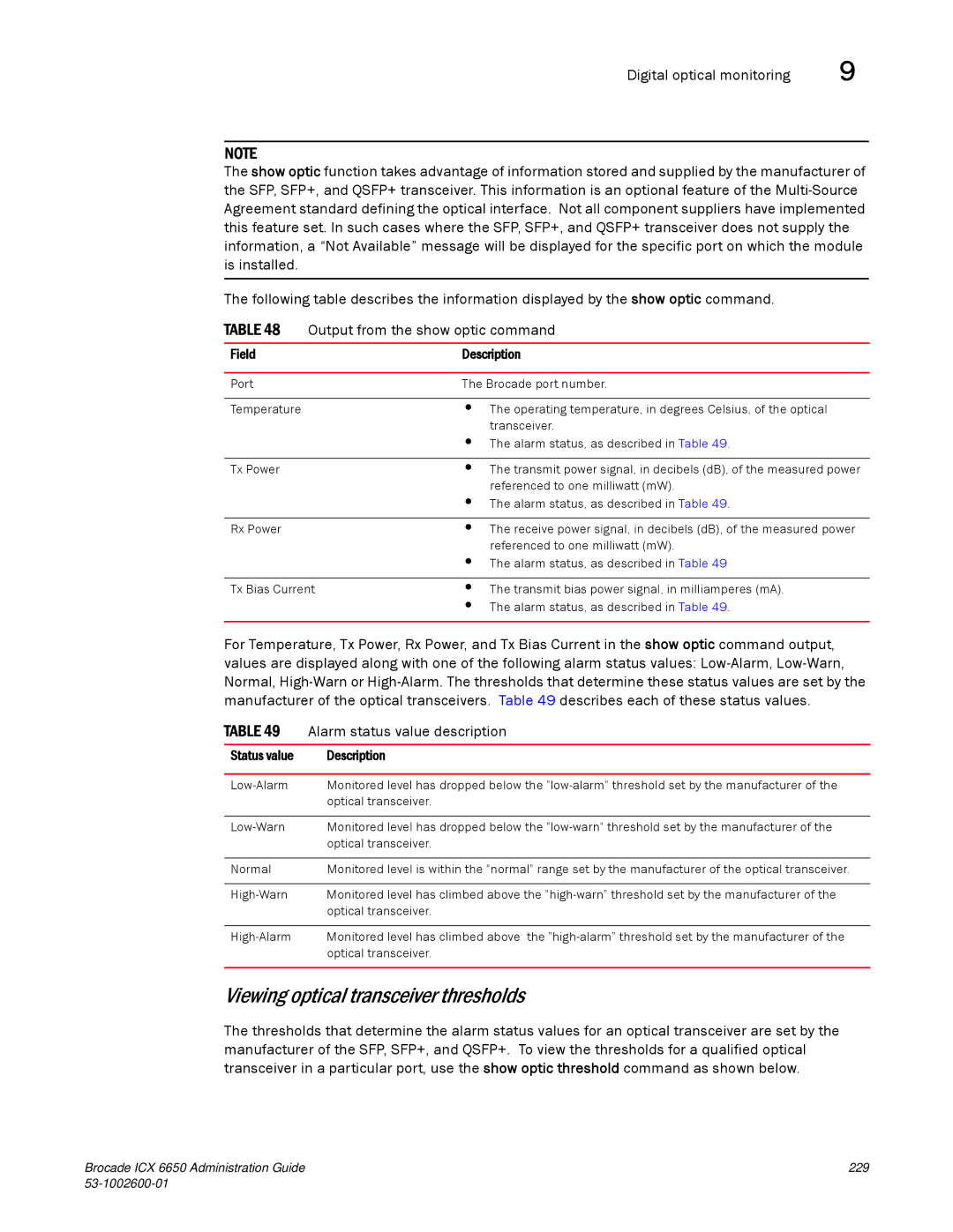
Digital optical monitoring
Digital optical monitoring configuration limitations
Setting the alarm interval
Displaying information about installed media
Viewing port statistics
Viewing configuration information
Basic system management
Viewing system information
NIAP-CCEVS certified Brocade equipment Ironware releases
Local user password changes
Xii Brocade ICX 6650 Administration Guide 53-1002600-01
Supported hardware and software
Audience
Brocade ICX 6650 slot and port numbering
Text formatting
Command syntax conventions
Command Option, option Argument, arg Arguments
Document conventions
Show WWN
Additional information
Related publications
Brocade resources
Document feedback
Getting technical help
Other industry resources
Brocade ICX 6650 slot and port numbering
How the management port works
Feature
This chapter
Management port overview
Syntax show interfaces brief management num
CLI Commands for use with the management port
Syntax show running-config interface management num
Syntax show interfaces management num
Syntax show statistics management num
Logging on through the CLI
Syntax show statistics brief management num
Online help
Command completion
Scroll control
Line editing commands
Using slot number, and port number with CLI commands
Ctrl+Key combination Description
Displaying lines containing a specified string
Searching and filtering output from CLI commands
Searching and filtering output from Show commands
CLI nomenclature on Brocade ICX 6650 models
Displaying lines starting with a specified string
Searching and filtering output at the --More-- prompt
Results of the search are displayed
Filtered results are displayed
Using special characters in regular expressions
Character Operation
Character Operation
Syntax alias
Creating an alias for a CLI command
Configuration notes for creating a command alias
Syntax unalias alias-name
Brocade ICX 6650 Administration Guide 53-1002600-01
Using slot number, and port number with CLI commands
Basic Port Parameters
Basic System Parameters
Basic system parameter configuration
Specifying an Snmp trap receiver
Entering system administration information
Snmp parameter configuration
Basic system parameter configuration
Syntax snmp-server host ip-addr0 1 string port value
Specifying a single trap source
Snmp Layer 2 traps
Setting the Snmp trap holddown time
Syntax no snmp-server enable traps holddown-time secs
Disabling Snmp traps
Displaying virtual routing interface statistics
Disabling Syslog messages and traps for CLI access
Syntax no snmp-server enable traps trap-type
Syntax no enable snmp ve-statistics
Syntax show logging
Examples of Syslog messages for CLI access
Disabling the Syslog messages and traps
Syntax no logging enable user-login
Cancelling an outbound Telnet session
Specifying an Sntp server
Syntax show sntp associations
Syntax no sntp poll-interval
Field Description
Syntax show sntp associations details
Output from the show sntp associations details command
Configuring the device as an Sntp server
Configuring the device as an Sntp server
Syntax show sntp status
Sntp server-mode authentication-key 2 $QHMiR3NzQA=
Syntax show sntp server-mode
Enabling broadcast mode for an Sntp client
Output from the show sntp server-modecommand
Displaying Sntp server information
Syntax sntp broadcast client
Setting the system clock
Syntax no clock summer-time
System time for daylight saving time. command
New start and end dates for US daylight saving time
Syntax sntp sync
Syntax no clock timezone us timezone-type
CLI banner configuration
Setting a message of the day banner
Limiting broadcast, multicast, and unknown unicast traffic
Syntax no banner motd require-enter-key
Use the no form of the command to disable the requirement
Syntax no banner incoming delimiting-character
Setting a privileged Exec CLI level banner
Local MAC address for Layer 2 management traffic
Syntax no banner execmode delimiting-character
Syntax port-name text
Basic port parameter configuration
Assigning a port name
Syntax no use-local-management-mac
Syntax speed-duplex value
Port speed and duplex mode modification
Port speed and duplex mode configuration syntax
Basic port parameter configuration
Syntax no speed-duplex 10g-full 1000-full-master
Maximum port speed application notes
Modifying port duplex mode
Port duplex mode configuration syntax
Value can be one of the following Full Half Auto default
Disabling or re-enabling flow control
Flow control configuration
Flow control configuration notes
Disabling or re-enabling a port
Syntax no flow-control
Negotiation and advertisement of flow control
Syntax no flow-control neg-on
Displaying flow-control status
Symmetric flow control on Brocade ICX 6650 devices
1G or 10G ports
About XON and Xoff thresholds
40G ports
Enabling and disabling symmetric flow control
Interpacket Gap IPG on a Brocade ICX 6650 switch
Changing the Gbps fiber negotiation mode
IPG configuration notes
Port priority QoS modification
Port flap dampening configuration
Port flap dampening configuration notes
Syntax gig-default neg-full-auto auto-gig neg-off
Displaying ports configured with port flap dampening
Configuring port flap dampening on an interface
Configuring port flap dampening on a trunk
Re-enabling a port disabled by port flap dampening
Syslog messages for port flap dampening
Syntax show link-error-disable all
Column Description
Types of loop detection
Recovering disabled ports
Port loopback detection configuration notes
Port loop detection
Syntax no loop-detection
Configuring a global loop detection interval
Configuring the device to automatically re-enable ports
Enabling loop detection
Clearing loop-detection
Specifying the recovery time interval
Syntax no errdisable recovery cause loop-detection
Syntax no errdisable recovery interval seconds
Syntax show loop-detection resource
Displaying loop detection resource information
FieldDescription
Loop Detection is Enabled
Syslog message due to disabled port in loop detection
Basic port parameter configuration
Feature Brocade ICX 6650
Operations, Administration, and Maintenance
Brocade ICX 6650 devices
Software versions installed and running on a device
OAM Overview
Determining the flash image version running on the device
Boot code version is shown in bold type
Displaying the boot image version running on the device
Displaying the image versions installed in flash memory
Software versions installed and running on a device
Use the following command syntax to verify the flash image
Flash image CLI commands
Flash image verification
Viewing the contents of flash files
Software upgrades
Image file types
Syntax copy flash console filename
Using Snmp to upgrade software
Using Snmp to upgrade software
Syntax show dir
Snmp-server community string ro rw
Software reboot
Software reboot
Displaying the boot preference
Software boot configuration notes
Loading and saving configuration files
Loading and saving configuration files
Syntax show boot-preference
Syntax no logging enable config-changed
Logging changes to the startup-config file
Preparing the configuration file
Copying a configuration file to or from a Tftp server
Dynamic configuration loading
Dynamic configuration usage considerations
CLI responds like this
Following command line will not initiate batch mode
Copying a file to an IPv6 Tftp server
Loading and saving configuration files with IPv6
Using the IPv6 copy command
Copying a file from the running or startup configuration
Copying a file to flash memory
Copying a file to the running or startup configuration
Loading and saving configuration files with IPv6
Copying a file from an IPv6 Tftp server
IPv6 ncopy command
IPv6 Tftp server file upload
Using Snmp to save and load configuration information
Syntax reload at hhmmss mm-dd-yyprimary secondary
Erasing image and configuration files
System reload scheduling
Reloading at a specific time
Reloading after a specific amount of time
Diagnostic error codes and remedies for Tftp transfers
Canceling a scheduled reload
Error Message Explanation and action Code
Network connectivity testing
Network connectivity testing
Pinging an IPv4 address
Network connectivity testing
Tracing an IPv4 route
Network connectivity testing
Ports on Demand Overview
Feature Brocade ICX
Ports on Demand terminology
PoD licensing configuration tasks
Ports on Demand terminology
PoD licensing rules
Obtaining a PoD license
Configuration task Reference
Brocade Software Portal Login window
Shows the Software Portal Login window
License Management Welcome window
PoD licensing configuration tasks
Brocade ICX 6650 Administration Guide 53-1002600-01
LID
Shows an example of the license query results
Front panel PoD
Transferring a PoD license
Syslog message information
Ports on Demand Licensing
PoD licenses
Rear panel Flexible Ports on Demand
Ports on Demand Licensing
License SKU License Name Function
Enabling ports on the front panel
Ports on Demand Licensing PoD licenses
Trial licenses are not available for PoD licensing
Syntax scp licensefileonhost user@IPaddresslicenseunit id
Example, the license is copied to unit
Example above, the license is copied to unit
Deleting a ICX6650-10G-LIC-POD license
Syntax show pod
Enabling ports on the rear panel
IPaddress variable is the address of the IPv4 Tftp server
Syntax no fpod-40g-enable group groupID
Disabling the FPoD ports on the rear panel
Enter the following command to disable the ports in group
Enable ports for group
Enable ports in group
Deleting a 10 GbE or 40 GbE license
Syntax license delete unit unitid all index licenseindex
Viewing information about PoD licenses
Viewing information about PoD licenses
Displaying general license information for PoD ports
Syntax show license
Syntax show license unit unitid index indexnumber
Syntax show license unit unitid
Field Description
Lic-Used
Field Description
40GigabitEthernet1/2/1 is up, line protocol is up
Viewing information about PoD licenses
IPv6 Configuration on Brocade ICX 6650 Switch
IPv6 copy Using the IPv6 copy command on
IPv6 addressing overview
Full Layer 3 IPv6 feature support
IPv6 address types
Address Description Address structure Type
IPv6 addressing overview IPv6 address types
IPv6 stateless auto-configuration
IPv6 CLI command support
IPv6 command Description Switch code Router code
Description Switch code Router code
IPv6 host address on a Layer 2 switch
Syntax ipv6 address ipv6-addresslink-local
Syntax no ipv6 enable
Syntax no ipv6 unicast-routing
Configuring basic IPv6 connectivity on a Layer 3 switch
IPv6 configuration on each router interface
Enabling IPv6 routing
Ospf
Configuring basic IPv6 connectivity on a Layer 3 switch
Configuring a link-local IPv6 address on an interface
Configuring an IPv6 anycast address on an interface
Configuring IPv4 and IPv6 protocol stacks
Syntax ip address ip-addresssub-net-masksecondary
Syntax no ipv6 access-list ACL name
Configuring IPv6 management ACLs
Specifying an IPv6 Snmp trap receiver
Restricting Snmp access to an IPv6 node
Configuring Snmp V3 over IPv6
Configuring Sntp over IPv6
IPv6 traceroute
IPv6 Telnet
Establishing a Telnet session from an IPv6 host
Syntax traceroute ipv6 ipv6-address
Defining an IPv6 DNS entry
Syntax no ipv6 dns domain-name domain name
Pinging an IPv6 address
Viewing IPv6 Snmp server addresses
Configuring an IPv6 Syslog server
Disabling IPv6 on a Layer 2 switch
Static IPv6 route configuration
Disabling router advertisement and solicitation messages
Configuring a static IPv6 route
Dest-ipv6-prefix parameter
Parameter Configuration details Status
Prefix-length parameter
IPv6 over IPv4 tunnels
IPv6 over IPv4 tunnel configuration notes
Configuring a manual IPv6 tunnel
IPv6 over IPv4 tunnels
Clearing IPv6 tunnel statistics
Syntax clear ipv6 tunnel number
Displaying IPv6 tunnel information
Displaying a summary of tunnel information
Displaying tunnel interface information
Syntax show interfaces tunnel number
Displaying interface level IPv6 settings
Display command above reflects the following configuration
Ecmp load sharing for IPv6
Ecmp load sharing for IPv6
Changing the maximum load sharing paths for IPv6
Disabling or re-enabling Ecmp load sharing for IPv6
Displaying Ecmp load-sharing information for IPv6
Syntax ipv6 icmp error-interval interval number-of-tokens
IPv6 Icmp feature configuration
Configuring Icmp rate limiting
IPv6 Icmp feature configuration
Syntax no ipv6 redirects
IPv6 neighbor discovery configuration
IPv6 neighbor discovery configuration
Enabling IPv6 Icmp redirect messages
Neighbor solicitation and advertisement messages
IPv6 neighbor discovery configuration notes
Neighbor discovery is not supported on tunnel interfaces
Neighbor redirect messages
Router advertisement and solicitation messages
Setting IPv6 router advertisement parameters
Here is another example with a specified range
Prefixes advertised in IPv6 router advertisement messages
Enabling and disabling IPv6 router advertisements
Setting flags in IPv6 router advertisement messages
Syntax no ipv6 nd suppress-ra
IPv6 MTU
Configuring reachable time for remote IPv6 nodes
Configuration notes and feature limitations for IPv6 MTU
IPv6 MTU
Changing the IPv6 MTU
Static neighbor entries configuration
Syntax no ipv6 mtu bytes
Syntax no ipv6 hop-limit number
Limiting the number of hops an IPv6 packet can traverse
IPv6 source routing security enhancements
Clearing global IPv6 information
Clearing IPv6 neighbor information
Clearing the IPv6 cache
Clearing global IPv6 information
Displaying IPv6 cache information
Displaying global IPv6 information
Clearing IPv6 routes from the IPv6 route table
Clearing IPv6 traffic statistics
Displaying IPv6 interface information
142 Brocade ICX 6650 Administration Guide 53-1002600-01
Icmp
Displaying IPv6 neighbor information
Displaying the IPv6 route table
Displaying local IPv6 routers
Syntax show ipv6 router
Displaying IPv6 TCP information
Port
Free TCP = percentage
Syntax show ipv6 tcp connections
= percentage
General IPv6 TCP connection fields
Location of the TCP
Syntax show ipv6 traffic
Displaying IPv6 traffic statistics
Field Description IPv6 statistics
ICMP6 statistics
Applies to received only
TCP statistics
Snmp overview
Snmp Access
Snmp community strings
Snmp community strings
Encryption of Snmp community strings
Adding an Snmp community string
Snmp-server community 1 encrypted-string rw
Syntax show snmp server
Displaying the Snmp community strings
Defining the engine id
Configuring your NMS
Configuring Snmp version 3 on Brocade ICX 6650 devices
User-based security model
Defining an Snmp group
Snmp version 3. If you want command
Syntax no snmp-server engineid local hex-string
Defining an Snmp user account
162 Brocade ICX 6650 Administration Guide 53-1002600-01
Syntax system-max view number-of-views
Defining Snmp views
Syntax no snmp-server view name mibtree included excluded
Snmp version 3 traps
To delete a view, use the no parameter before the command
Snmp version 3 traps
Trap MIB changes
Defining the UDP port for Snmp v3 traps
Backward compatibility with SMIv1 trap format
Restricting Snmp Access to an IPv6 Node
Specifying an IPv6 host as an Snmp trap receiver
Snmp v3 over IPv6
Syntax show snmp engineid
Displaying Snmp Information
Displaying the Engine ID
Displaying Snmp Information
Syntax show snmp group
Displaying Snmp groups
Displaying user information
Interpreting varbinds in report packets
Snmp v3 configuration examples
Snmp v3 configuration examples
Simple Snmp v3 configuration
More detailed Snmp v3 configuration
170 Brocade ICX 6650 Administration Guide 53-1002600-01
FDP Overview CDP packets
FDP Overview
Enabling FDP at the interface level
FDP configuration
Changing the FDP update timer
Enabling FDP globally
Displaying neighbor information
Syntax no fdp timer secs
Displaying FDP information
Changing the FDP hold time
Entry addresses
This line Displays
Brocade ICX 6650 Administration Guide 175 53-1002600-01
Clearing FDP and CDP neighbor information
Clearing FDP and CDP information
Displaying FDP information for an interface
Displaying FDP and CDP statistics
Clearing FDP and CDP statistics
CDP packets
Enabling interception of CDP packets globally
Enabling interception of CDP packets on an interface
Displaying neighbors
Displaying CDP information
Syntax show fdp entry * device-id
Displaying CDP entries
Clearing CDP information
To clear CDP statistics, enter the following command
Displaying CDP statistics
Lldp and LLDP-MED
Lldp terms used in this chapter
Lldp terms used in this chapter Supported Lldp features
Illustrates Lldp connectivity
Lldp overview
Benefits of Lldp
LLDP-MED overview
LLDP-MED overview
LLDP-MED connectivity
Benefits of LLDP-MED
Lldp operating modes
Lldp transmit mode
General Lldp operating principles
LLDP-MED class
Lldp packets
Lldp receive mode
Lldp TLVs
TLV support
Organizationally-specific TLVs
Chassis ID TLV is always the first TLV in the Lldpdu
LLDP-MED TLVs
Mandatory TLVs
Chassis ID
TTL value
Port ID TLV packet format
Syslog messages
MIB support
MIB support TTL TLV format is shown below
Global task Default behavior / value when Lldp is enabled
Lldp configuration
Lldp configuration notes and considerations
Lldp configuration
Enabling and disabling Lldp
Changing a port Lldp operating mode
Enabling support for tagged Lldp packets
Enabling and Disabling Transmit Only Mode
Enabling and disabling receive only mode
Specifying the maximum number Lldp neighbors per device
Maximum number of Lldp neighbors
Syntax no lldp max-total-neighbors value
Specifying the maximum number Lldp neighbors per port
Enabling Lldp Snmp notifications and Syslog messages
Syntax no lldp max-neighbors-per-port value
Changing the minimum time between Lldp transmissions
Syntax no lldp transmit-delay seconds
Syntax no lldp snmp-notification-interval seconds
Syntax no lldp transmit-hold value
Changing the interval between regular Lldp transmissions
Changing the holdtime multiplier for transmit TTL
Syntax no lldp transmit-interval seconds
General system information for Lldp
Syntax no lldp reinit-delay seconds
Changing the minimum time between port reinitializations
Lldp TLVs advertised by the Brocade device
Management Address
System capabilities
Port description
System description
System name
Capabilities
Vlan name
Link aggregation TLV
Untagged Vlan ID
MAC and PHY configuration status
Maximum frame size
LLDP-MED configuration
LLDP-MED configuration
This section provides the details for configuring LLDP-MED
Default behavior / value
Syntax no lldp med fast-start-repeat-count value
Changing the fast start repeat count
Coordinate-based location
Defining a location id
Example coordinate-based location advertisement
Example coordinate-based location configuration
Type value elem CA type value elem CA type value
Configuring civic address location
LLDP-MED configuration Elements used with civic address
Description Acceptable values / examples Type
Example civic address location advertisement
Configuring emergency call service
Number variable is a number from 10 to 25 digits in length
Defining an LLDP-MED network policy
LLDP-MED network policy configuration syntax
Example ECS Elin location advertisements
216 Brocade ICX 6650 Administration Guide 53-1002600-01
LLDP-MED capabilities
LLDP-MED attributes advertised by the Brocade device
Lldp configuration summary
Displaying Lldp statistics and configuration settings
LLDP-MED attributes advertised by the Brocade device
Syntax show lldp
Displaying Lldp statistics
Syntax show lldp statistics
Clear lldp statistics all command was issued
Syntax show lldp neighbors
Displaying Lldp neighbors
Displaying Lldp neighbors detail
Displaying Lldp configuration details
Resetting Lldp statistics
Clearing cached Lldp neighbor information
Syntax no optical-monitor
Digital optical monitoring configuration limitations
Digital optical monitoring
Enabling digital optical monitoring
Displaying information about installed media
Setting the alarm interval
Syntax no optical-monitor alarm-interval
Empty
Syntax show media slot slot ethernet stack-unit/slot/port
Viewing optical monitoring information
Status value Description
Viewing optical transceiver thresholds
Syntax show optic threshold stack-unit/slot/port
Syslog messages for optical transceivers
Syslog
Displaying Syslog messages
About Syslog messages
Syntax terminal monitor
Enabling real-time display of Syslog messages
Enabling real-time display for a Telnet or SSH session
Syntax no logging console
Displaying real-time Syslog messages
Syslog service configuration
Displaying the Syslog configuration
Syslog service configuration
Field Definition
Static and dynamic buffers
Time stamps
Clearing log entries
Syntax clear logging dynamic-buffer static-buffer
Brocade ICX 6650 Administration Guide 237 53-1002600-01
Syntax no logging on udp-port
To specify a Syslog server, enter the logging host command
Disabling or re-enabling Syslog
Specifying a Syslog server
Syntax no logging buffered level num-entries
Specifying an additional Syslog server
Disabling logging of a message level
Changing the number of entries the local buffer can hold
Changing the log facility
Local buffer configuration notes
Syntax logging facility facility-name
Displaying TCP or UDP port numbers in Syslog messages
Displaying interface names in Syslog messages
Syntax no Ip show-portname
Syslog reboot configuration considerations
Retaining Syslog messages after a soft reboot
Clearing the Syslog messages from the local buffer
Viewing system information
Basic system management
Syntax show version
Viewing configuration information
Port statistics
Viewing port statistics
Syntax show option
Syntax show statistics ethernet stack-unit/slot/port
Parameter Description
Basic system management Port statistics
Statistics
Viewing STP statistics
Syntax clear option
Clearing statistics
Syntax show interface ethernet stack-unit/slot/port
Viewing egress queue counters
Syntax clear statistics ethernet stack-unit/slot/port
Rmon support
Maximum number of entries allowed Rmon control table
Clearing the egress queue counters
ParameterDefinition
Statistics Rmon group
Rmon support
Syntax show rmon statistics ethernet stack-unit/slot/port
Parameter Definition
Rmon support Export configuration and statistics
History Rmon group
Alarm Rmon group
Event Rmon group
SFlow version
SFlow
Extended router information
SFlow support for IPv6 packets
Extended gateway information
SFlow and CPU utilization
SFlow configuration considerations
IPv6 packet sampling
SFlow and hardware support
SFlow and source port
Configuring and enabling sFlow
SFlow and sampling rate
Specifying an sFlow collector on IPv4 devices
Specifying the collector
Syntax no sflow destination ip-addrdest-udp-port
Syntax no sflow destination ipv6 ip-addrdest-udp-port
Changing the polling interval
Changing the sampling rate
Specifying an sFlow collector on IPv6 devices
Module rate
Configuration considerations
Configured rate and actual rate
Change to global rate
Changing the sampling rate on a port
Changing the default sampling rate
Syntax no sflow sample num
Changing the sampling rate of a module
Changing the sampling rate for a trunk port
Syntax no sflow source-port num
Command syntax for enabling sFlow forwarding
Enabling sFlow forwarding
Changing the sFlow source port
Syntax no sflow enable Syntax no sflow forwarding
SFlow version 5 feature configuration
Syntax no sflow agent-ip ipv4-addr
Specifying the sFlow version format
Specifying the sFlow agent IP address
Specifying the version used for exporting sFlow data
Syntax no sflow export system-info
Specifying the maximum flow sample size
Syntax no sflow version 2
Syntax no sflow max-packet-size size
Specifying the sampling rate for exported CPU-directed data
Displaying sFlow information
Enabling the sFlow agent to export CPU-directed data
Syntax no sflow export cpu-traffic
Syntax show sflow
SFlow SFlow information
Clearing sFlow statistics
Syntax clear statistics
Utilization list for an uplink port
Utilization list for an uplink port command syntax
Utilization list for an uplink port
Syntax show relative-utilization num
Displaying utilization percentages for an uplink
272 Brocade ICX 6650 Administration Guide 53-1002600-01
Mac-address on portnum
Brocade Syslog messages
Message Explanation
Fan num, location , failed
Syslog messages Brocade Syslog messages
Addr memory-address
PCI-config-register-offset
PCI-bus-number, Dev
PCI-device-number, Reg Offset
Username from session-id filter
Message level Explanation
Level shutdown-degrees C degrees
From session-id
Root ID root-id
User username from session-id
Stp-state
Vlan-id
MAC address any
MAC address any, dst mac = Destination
IP=ipaddr
Fan speed
Port-number
Unit/slot/port on Vlan vlan-id
Unit/slot/port to
Unit/slot/port on VLANs vlan-id to Vlan-id
Unit/slot/port on vlan-id
Mac-address RootPort portnum
Mac-address MgmtPriChg
Mac-address MsgAgeExpiry
Vlan vlan-id interface portnum STP
DOT1X Port portid Mac macaddress
Portnum
Rid router-id, intf addr ip-addr
Macaddress on port portid
State ospf-state
286 Brocade ICX 6650 Administration Guide 53-1002600-01
Pkt type pkt-type
Type
Ip-addr, pkt type type
Rid router-id, limit num
LSA id lsa-id, LSA rid lsa-router-id
Area area-id, LSA type lsa-type
Ospf-state
Brocade ICX 6650 Administration Guide 291 53-1002600-01
Interface configuration error has occurred
Nbr ip-addr, state ospf-state
Rid router-id, area area-id
Rid router-id, nbr addr ip-addr
Mac-address
State vrrp-state
Mac-addr interface portnum
Portnum src macaddr mac-addr
List ACL-num denied ip-proto
Ethernet portnum mac-addr
Eportnum, address mac-address
Chassis temperature has risen above the warning level
298 Brocade ICX 6650 Administration Guide 53-1002600-01
NIAP-CCEVS certified Brocade equipment Ironware releases
Local user password changes
Brocade product Brocade IronWare Discussed Software version
300 Brocade ICX 6650 Administration Guide 53-1002600-01
Index
Clear fdp table, 176
Lldp advertise mac-phy-config-status ports
Lldp enable receive ports
Ipv6 nd prefix-advertisement,134
Brocade ICX 6650 Administration Guide 303 53-1002600-01
FDP
Icmp
131
LLDP-MED
266
Snmp
SSH
XON and Xoff thresholds
312 Brocade ICX 6650 Administration Guide 53-1002600-01