SPECIFICATIONS
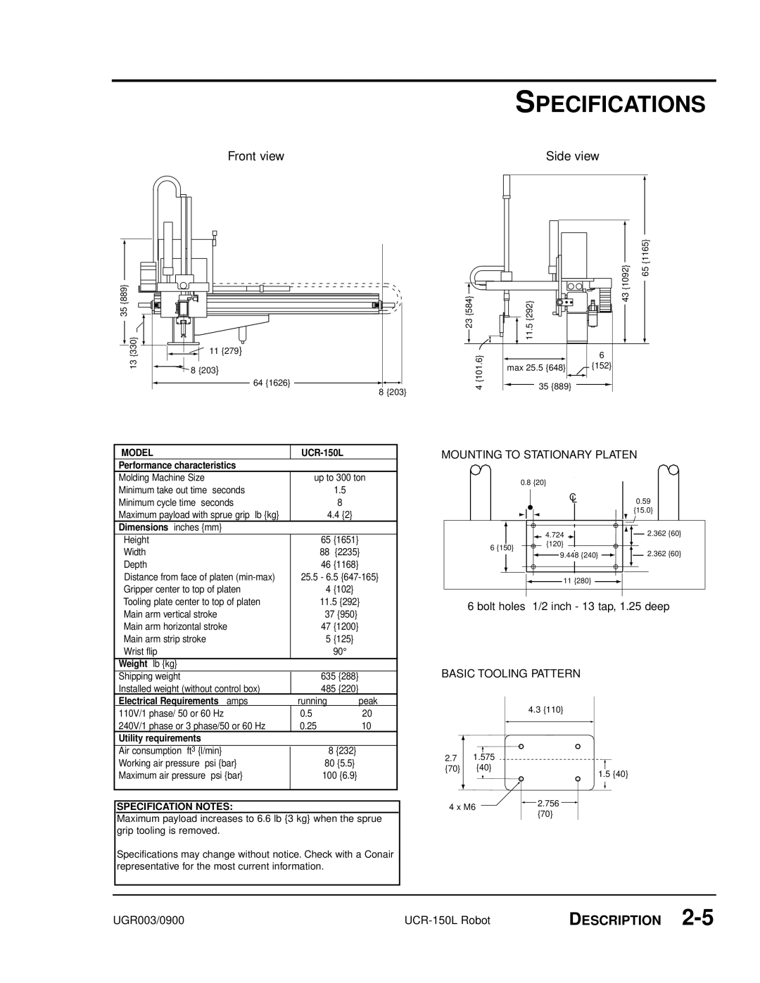
Front view | Side view |
|
|
35 {889} 13 {330}
11 {279}
8 {203}
64 {1626}
8 {203}
23 {584}
4 {101.6}
| {1092} | 65 {1165} |
{292} | 43 |
|
11.5 |
|
|
| 6 |
|
max 25.5 {648} | {152} |
|
35 {889} |
|
|
| MODEL | |||
| Performance characteristics |
|
|
|
| Molding Machine Size | up to 300 ton | ||
| Minimum take out time seconds |
| 1.5 |
|
| Minimum cycle time seconds |
| 8 |
|
| Maximum payload with sprue grip lb {kg} | 4.4 {2} |
| |
| Dimensions inches {mm} |
|
|
|
| Height | 65 | {1651} |
|
| Width | 88 | {2235} |
|
| Depth | 46 | {1168} |
|
| Distance from face of platen | 25.5 - 6.5 |
| |
| Gripper center to top of platen | 4 | {102} |
|
| Tooling plate center to top of platen | 11.5 {292} |
| |
| Main arm vertical stroke | 37 {950} |
| |
| Main arm horizontal stroke | 47 | {1200} |
|
| Main arm strip stroke | 5 | {125} |
|
| Wrist flip |
| 90° |
|
| Weight lb {kg} |
|
|
|
| Shipping weight | 635 {288} |
| |
| Installed weight (without control box) | 485 {220} |
| |
| Electrical Requirements amps | running | peak |
|
MOUNTING TO STATIONARY PLATEN
| 0.8 {20} |
| |
| C | 0.59 | |
| L | ||
|
| {15.0} | |
| 4.724 | 2.362 {60} | |
6 {150} | {120} |
| |
9.448 {240} | 2.362 {60} | ||
| |||
| 11 {280} |
|
6 bolt holes 1/2 inch - 13 tap, 1.25 deep
BASIC TOOLING PATTERN
110V/1 phase/ 50 or 60 Hz | 0.5 | 20 |
240V/1 phase or 3 phase/50 or 60 Hz | 0.25 | 10 |
Utility requirements |
|
|
Air consumption ft3 {l/min} |
| 8 {232} |
Working air pressure psi {bar} |
| 80 {5.5} |
Maximum air pressure psi {bar} |
| 100 {6.9} |
|
|
|
SPECIFICATION NOTES:
Maximum payload increases to 6.6 lb {3 kg} when the sprue grip tooling is removed.
Specifications may change without notice. Check with a Conair representative for the most current information.
2.71.575 {70} {40}
4 x M6
4.3 {110}
1.5 {40}
![]() 2.756
2.756 ![]() {70}
{70}
UGR003/0900 | DESCRIPTION |