Manuals
/
Dell
/
Computer Equipment
/
Printer
Dell
2330dn
service manual
Models:
2330dn
1
129
170
170
Download
170 pages
19.29 Kb
126
127
128
129
130
131
132
133
Specification
Install
Error messages
Diagram of the printer menus
Error Description Action
Maintenance
Configuration menu Config Menu
Symptom tables
Diagnostics menu
Front access door removal
Page 129
Image 129
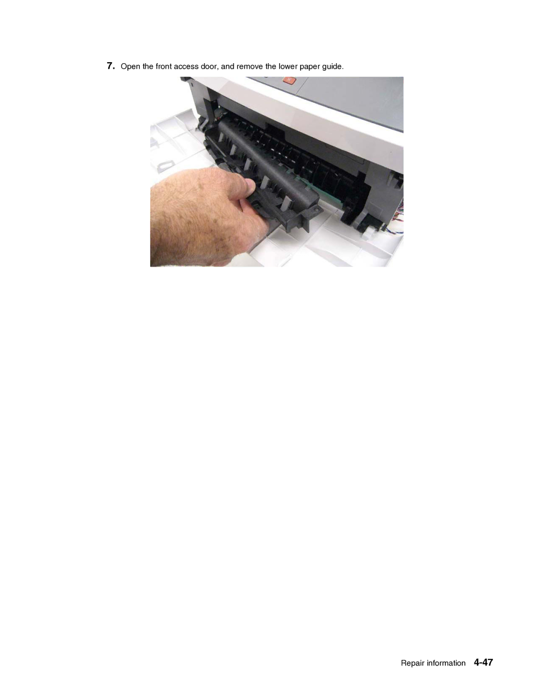
7.
Open the front access door, and remove the lower paper guide.
Repair information
4-47
Page 128
Page 130
Page 129
Image 129
Page 128
Page 130
Contents
Dell 2330d/dn
Page
Table of Contents
Page
Locations and connections
Page
Laser
Laser notice
Avis relatif à l’utilisation de laser
Avvertenze sui prodotti laser
Declaração sobre Laser
Avisos sobre el láser
Laserinformatie
Lasermeddelelse
Huomautus laserlaitteesta
Laserilmoitus
Laser-notis
Laser-melding
Avís sobre el Làser
Page
Xii
Consignes de sécurité
Safety information
Norme di sicurezza
Sicherheitshinweise
Pautas de Seguridad
Informações de Segurança
Xiv
Informació de Seguretat
Xvi
Conventions
General information
Maintenance approach
Overview of the operator panel
Specifications
Print quality settings
Memory
Connectivity and compatibility
Html including Dbcs Direct image Compatibility
Standard local connections Parallel
Media trays and supply capacity
Types of print media
Source Sizes Types Weight Input capacity* sheets
Paper path
Tips on preventing jams
Tools
Acronyms
Page
Start
Power-On Self Test Post sequence
Indicator light
Overview of the operator panel and menus
If the light is Printer is
Button or control panel item Function
Buttons
Display
Diagram of the printer menus
User attendance messages
Messages and error codes
User attendance messages
Message Action
Message to clear
Do not Power OFF
Cartridge error messages
Paper jam error codes 200-series
Error Description Action
Failed Small GAP or no GAP JAM Recovery
Rear exit guide. See Rear exit guide assembly
Guide. See Rear exit guide assembly with sensor
Paper input and duplex sensor assembly
Failed to feed from manual feeder. Pages in the paper
Error Description Action Engine software service errors
Service error codes
DC pick motor errors
Transfer service errors
Fan service errors
Toner service errors
Printhead service errors
Transport motor service errors
Power supply service errors
Controller board and operator panel service errors
Firmware or controller board errors
Memory and emulation errors
Network errors
Other errors
Symptom tables
Post symptom table
Symptom Action
See Solving print quality problems on
Printer symptom table
Service checks
Controller board service check
Post Power-On Self Test
Cover interlock switch service check
Cooling fan service check
Verify main power to controller board
Pins Voltage
Dead machine service check
Fuser service check
LVPS/HVPS service check
Lvps portion of board
J17 pins Voltages
Main motor service check
Paper feed service checks
Operator panel service check
LCD Operator panel service check
Paper jam error indication during Post
Media skews
Media never picks
Media trees, wrinkles, stacks poorly, or curls
Parallel or USB port service check
Using print quality test pages
Print quality service checks
Blank
Press to Prt Quality Pgs
Heavy background
Black
Poor fusing of image
Partial blank image/white spots no repeating pattern
Variation in image density horizontally across
Light print
White or black lines or bands
Toner on back
Solving print quality problems
Also, see Blank page on
Toner Low
Load Paper displays
Transfer roll service check
Printhead service check
Tray 2 service check
Printing menus
Accessing service menus
Entering Configuration Menu
Configuration menu Config Menu
Configuration menu settings
Available menus
Print quality pages Prt Quality Pgs
Reset photoconductor maintenance counter Reset PC Cnt
Reports
Panel Menus
Factory Defaults
Demo Mode
Exit Configuration Menu Exit Config Menu
Energy Conserve
Entering Diagnostics menu
Diagnostics menu
Diagnostic menu settings
Available tests
Margins
Registration
Quick Test
Print tests
Input sources
Print Quality Pages Prt Quality Pgs
LCD Test
Hardware tests
Button Test
Dram Test
Top Margin
Duplex tests
Left Margin
Sensor Test
Input tray tests
Duplex Feed
Feed Tests
Output bin tests
Base sensor test B. sensor test
Bin Mailbox
Defaults
Printer setup
Printed Page Count Page Count
Permanent Page Count Perm Page Count
EP setup
Event log
Exit Diagnostics
Print Log
Clear Log
Quick Test Sample only use actual sheet
Printhead assembly electronic adjustment
To adjust the printhead
Printhead assembly mechanical adjustment
Page
Handling ESD-sensitive parts
Repair information
Removal procedures
ACM pick tire roller removal
Page
Bezel removal
Controller board removal
Page
Cover open sensor
Door mount removal
Page
Duplex removal
Page
Duplex/main motor gear drive interface removal
Page
Page
Fan removal
Front access door removal
Page
Page
Fuser removal
Page
Page
Left side cover removal
Swing the cover open, and lift to remove the left side cover
Lower front cover removal
Page
LVPS/HVPS removal
Page
Page
Main motor gear drive removal
Page
Manual feed clutch removal
Page
Manual feed solenoid removal
Page
Installation note
Media ACM ASM feeder removal
Page
Page
Media feed clutch with cable removal
Page
Media manual input sensor
Re-installation note
Page
Multipurpose feeder MPF removal
Page
Page
Multipurpose feeder MPF feed clutch removal
Page
Nameplate removal
Operator panel removal
Paper input and duplex sensor assembly removal
Printhead removal
Rear door and rear cover removal
Tilt the rear cover, and remove Repair information
BBB
Page
Right side cover assembly removal
Page
Toner level sensor removal
Top cover assembly removal
Page
Transfer roll removal
Upper front guide assembly removal
Wear strip tray 1 and 250-sheet tray 2 removal
Wear strip 550-sheet tray 2 removal
Locations
Front view
Rear view
Controller board connector pin values
Cooling fan
LVPS/HVPS
Lubrication specifications
Safety inspection guide
Page
How to use this parts catalog
Asm- Part Index number Units/ Units/ mach FRU Description
Machine type Description Model
Assembly 1 Covers
Asm Part Units Description Index Number
Assembly 2 Electronics
Assembly 2 Electronics
Assembly 3 Frame
Assembly 3 Frame
256MB Dimm
Assembly 4 Options
Assembly 5 Power cords
Page
Index
Page
Part number index
Page
Dell 2330d/2330dn recommended spare part list
Power Sources
Top
Page
Image
Contents