Printhead removal
1.Remove the top cover. See “Top cover assembly removal” on page
2.Remove the right side cover. See “Right side cover assembly removal” on page
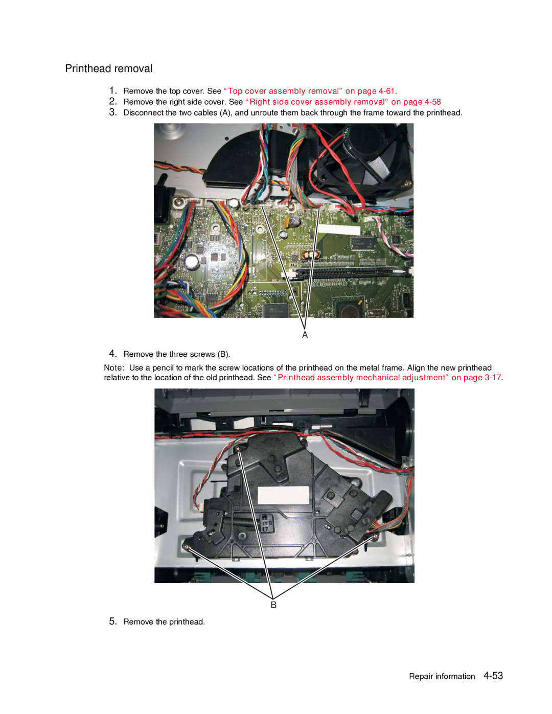
3.Disconnect the two cables (A), and unroute them back through the frame toward the printhead.
A
4.Remove the three screws (B).
Note: Use a pencil to mark the screw locations of the printhead on the metal frame. Align the new printhead relative to the location of the old printhead. See “Printhead assembly mechanical adjustment” on page
B
5.Remove the printhead.
Repair information