Main motor service check
FRU | Action |
|
|
|
| ||
|
|
|
|
| |||
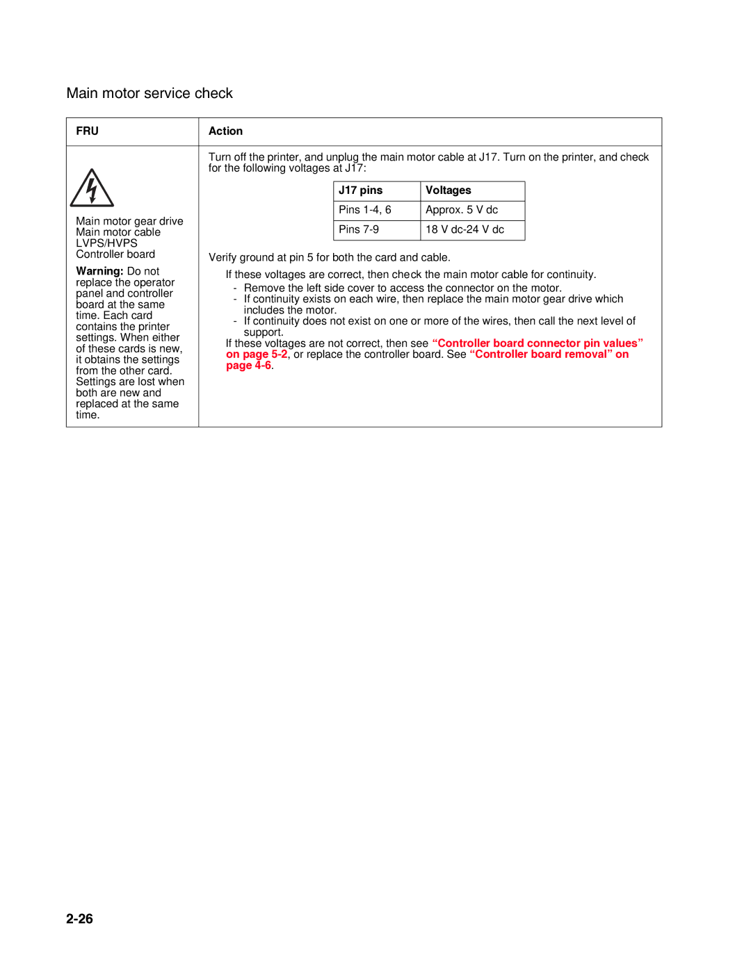
| Turn off the printer, and unplug the main motor cable at J17. Turn on the printer, and check | ||||||
| for the following voltages at J17: |
|
| ||||
|
|
|
|
|
|
| |
|
|
|
| J17 pins | Voltages |
| |
|
|
|
|
|
|
| |
Main motor gear drive |
|
|
| Pins | Approx. 5 V dc |
| |
|
|
|
|
|
| ||
|
|
| Pins | 18 V |
| ||
Main motor cable |
|
|
|
| |||
LVPS/HVPS |
|
|
|
|
|
| |
|
|
|
|
|
| ||
Controller board | Verify ground at pin 5 for both the card and cable. | ||||||
Warning: Do not | • | If these voltages are correct, then check the main motor cable for continuity. | |||||
replace the operator |
| - | Remove the left side cover to access the connector on the motor. | ||||
panel and controller |
| ||||||
| - | If continuity exists on each wire, then replace the main motor gear drive which | |||||
board at the same |
| ||||||
|
| includes the motor. |
|
| |||
time. Each card |
|
|
|
| |||
| - If continuity does not exist on one or more of the wires, then call the next level of | ||||||
contains the printer |
| ||||||
|
| support. |
|
| |||
settings. When either |
|
|
|
| |||
• | If these voltages are not correct, then see “Controller board connector pin values” | ||||||
of these cards is new, | |||||||
| on page | ||||||
it obtains the settings |
| ||||||
| page |
|
| ||||
from the other card. |
|
|
| ||||
|
|
|
|
|
| ||
Settings are lost when |
|
|
|
|
|
| |
both are new and |
|
|
|
|
|
| |
replaced at the same |
|
|
|
|
|
| |
time. |
|
|
|
|
|
| |
|
|
|
|
|
|
| |
