Memory Locations and Replacement Procedures
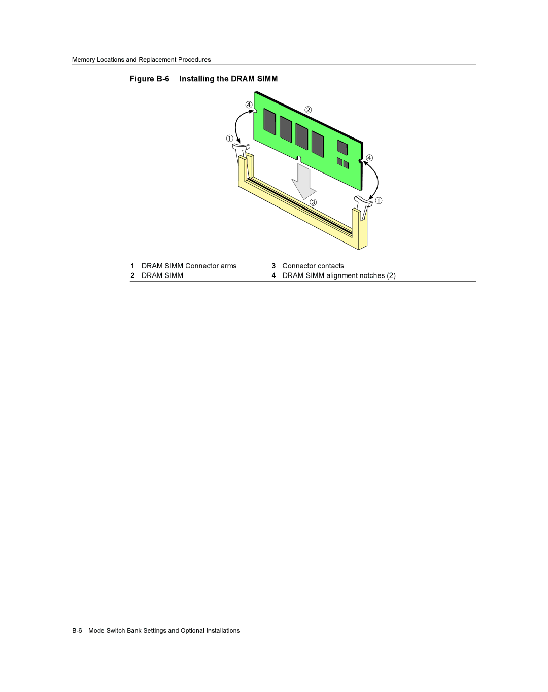
Figure B-6 Installing the DRAM SIMM
ÃÁ
À ![]()
Ã
 ![]() À
1 | DRAM SIMM Connector arms | 3 | Connector contacts |
2 | DRAM SIMM | 4 | DRAM SIMM alignment notches (2) |
Memory Locations and Replacement Procedures
ÃÁ
À ![]()
Ã
 ![]() À
1 | DRAM SIMM Connector arms | 3 | Connector contacts |
2 | DRAM SIMM | 4 | DRAM SIMM alignment notches (2) |