Connecting to COM Port for Local Management
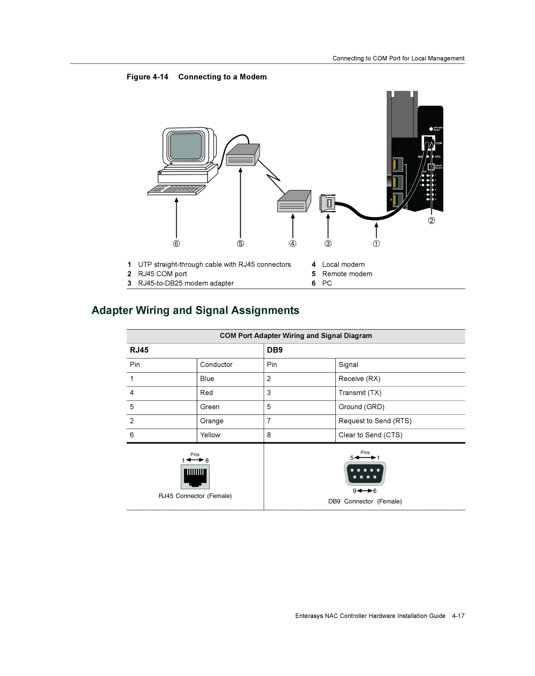
Figure 4-14 Connecting to a Modem
1 | UTP | 4 | Local modem |
2 | RJ45 COM port | 5 | Remote modem |
3 | 6 | PC |
Adapter Wiring and Signal Assignments
COM Port Adapter Wiring and Signal Diagram
RJ45 |
| DB9 |
|
|
Pin | Conductor | Pin | Signal |
|
1 | Blue | 2 | Receive (RX) | |
4 | Red | 3 | Transmit (TX) | |
5 | Green | 5 | Ground (GRD) | |
2 | Orange | 7 | Request to Send (RTS) | |
6 | Yellow | 8 | Clear to Send (CTS) | |
| Pins |
| Pins |
|
|
| 5 | 1 | |
1 | 8 |
| ||
|
|
| ||
RJ45 Connector (Female) |
| 9 | 6 | |
| DB9 Connector | (Female) | ||
|
|
| ||
Enterasys NAC Controller Hardware Installation Guide