Connecting to the Network
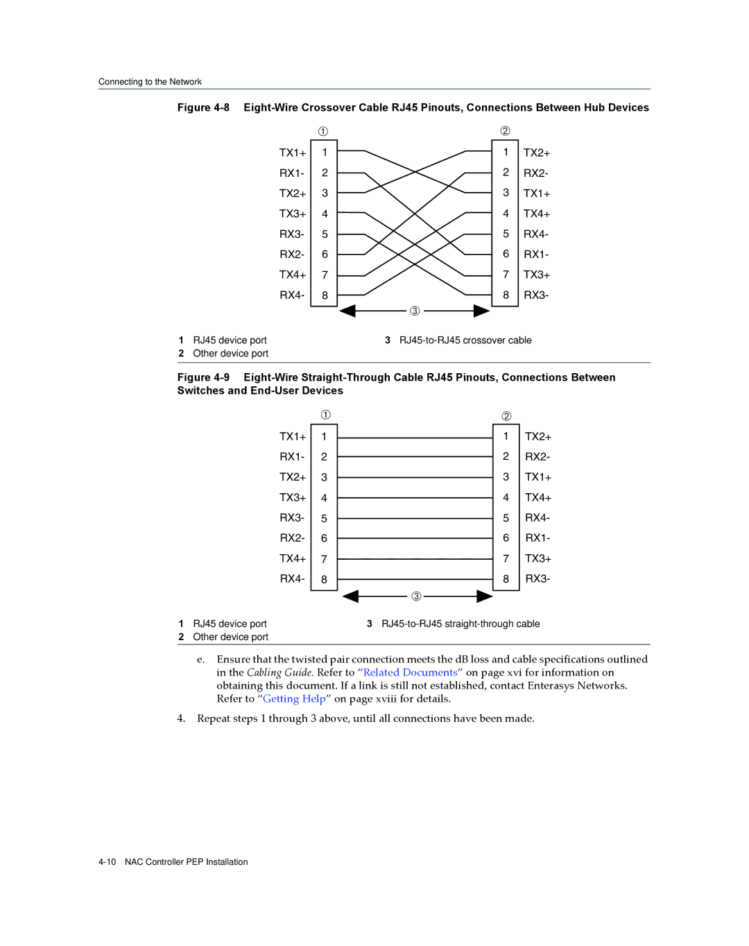
Figure 4-8 Eight-Wire Crossover Cable RJ45 Pinouts, Connections Between Hub Devices
| À |
TX1+ | 1 |
RX1- | 2 |
TX2+ | 3 |
TX3+ | 4 |
RX3- | 5 |
RX2- | 6 |
TX4+ | 7 |
RX4- | 8 |
|
|
1RJ45 device port
2Other device port
Á
1 | TX2+ |
2 | RX2- |
3 | TX1+ |
4 | TX4+ |
5 | RX4- |
6 | RX1- |
7 | TX3+ |
8 | RX3- |
Â
3
Figure 4-9 Eight-Wire Straight-Through Cable RJ45 Pinouts, Connections Between Switches and End-User Devices
À
TX1+ 1 RX1- 2 TX2+ 3 TX3+ 4 RX3- 5 RX2- 6 TX4+ 7 RX4- 8
Â
Á
1TX2+
2 RX2-
3 TX1+
4 TX4+
5 RX4-
6 RX1-
7 TX3+
8 RX3-
1 RJ45 device port | 3 |
2Other device port
e.Ensure that the twisted pair connection meets the dB loss and cable specifications outlined in the Cabling Guide. Refer to “Related Documents” on page xvi for information on obtaining this document. If a link is still not established, contact Enterasys Networks. Refer to “Getting Help” on page xviii for details.
4.Repeat steps 1 through 3 above, until all connections have been made.